This Multi-function timer circuit can be used to generate many different timing outputs at different desired ranges.
A timer is practically unachievable without IC 555 or counter ICs along the lines of CD4029 or CD4060.
How the Circuit Works
The simple mutifunction timer circuit in this article takes advantage of an inverter rather for accomplishing the same duty.
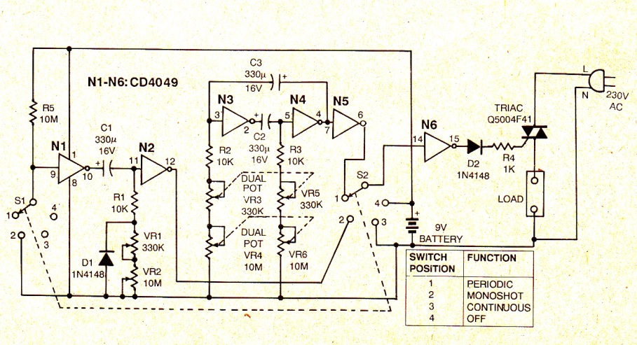
As revealed in the projected multifunction timer circuit, gate N1 together with C1, R1, VR1 and VR2 shapes 21 monostable multivibrator.
Each time S1 and S2, which happen to be ganged, come in point 2, input at gate N1 is retained low and thus as a result the output of gate N1 evolves into high.
This high output charges C1 by means of series association of R1, VR1 and VR2.
Simultaneously output of gate N2, which happens to be low, is directed at gate N6 and end result of gate N6 gets high.
The high output causes the triac along with the power is applied to the load.
After a while period of T = 0.7 x C1 (R1 + VR1 + VR2), at the output of gate N6 ends up being low so the triac inhibits conducting. Thereby this section of the circuit works in monoshot format.
Each time S1and S2 have reached set 1, the input of gate N6 is in touch with the astable multivibrator developed around gates N3 and N4.
Hence, the load is discontinued periodically.
In this case VR3 is ganged with VR5, and VR4 is ganged with VR6 to produce a square wave.
Duty cycle of the operation could be changed simply by eliminating the gang design (since the at charging and discharging period is going to be unique).
Here gates N2 and N5 are like working as buffers.
Once S1 and S2 have been in spot 3, the input of gate N6 is grounded and consequently the output of N6 continues as high provided thats the switches stay in this position.
Therefore, the triac continues to be on while the current runs continually by way of the load.
Eventually, any time S1 and S2 stay in position 4, the input of N6 is attached to Vcc on account of which the output stays at logic 0.
The triac is unable to operate which means that you have no current in the load.
330k pots are supposed to be calibrated for 0 to 60 seconds and 10M pots calibrated for 0 to 30 minutes.
As a result, anybody can attain any specific expected timing from 0 to 30 minutes.
Application of tantalum capacitors unquestionably improves the reliability of this multifunction timer circuit, nevertheless the expense might also go up.
Standalone on/off switch is not essential due to the fact that stand-by mode intake is just a few microamperes.
In full load situation, the circuit draws around 5 to 6 mA current guaranteeing a lifetime for the battery.
This particular timer switch work extremely well as a time regulator for washing machines, heaters and for system control associating short timing and so on.
This simple multi-function timer circuit could possibly be quickly configured on a general-purpose PCB. It will cost you around $1, without battery source.
thank you very good