This telephone amplifier circuit saves the trouble of holding the telephone handset while talking.
It is also very useful when a group of people want to listen to the telephone conversation.
Under these conditions, all one has to do is to switch on the telephone amplifier and listen to the amplified voice of the caller from the speaker.
The major and the foremost advantage of the unit is that no electrical connections with the telephone are required.
The telephone pickup coil, placed close to the telephone, picks up the signal (conversation) all by itself.
Telephone pick up coil is a coil of about 3000 turns of 38 S.W.G (Standard wire gauge) copper enameled wire wound on a 2 inch diameter, plastic or paper former.
The sensitivity of the unit depends upon the pickup coil and hence should be made with good care.
This telephone pickup coil, when placed close to the telephone, picks up. (by mutual induction) the audio frequency variations of currents produced by the telephone microphone.
These signals through the coupling, are fed to the IC amplifier for amplification.
The circuit for the telephone amplifier unit consists of a single IC and a few other external components.
The output signal, after amplification, is of about 400 mv in strength, This much output is sufficient to drive a small loud speaker.
After wiring the unit, connect the pickup coil to the input of the amplifier with the aid of shielded wires.
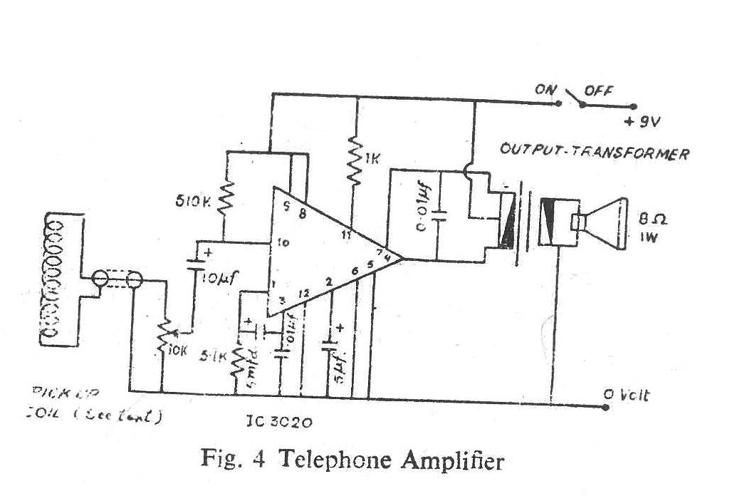
Set the volume control at maximum position (see fig. 4). Switch on the supply.
Pick up the telephone pick up coil and place it near the telephone receiver. The telephone amplifier unit should be placed away from the coil so as to prevent feed back.
Now lift the telephone and talk over it. At the same time position the coil to a point where maximum output is heard.
Mark the position and fix the coil. The current drain of the amplifier is pretty low and hence the battery used lasts for long time.
However, a battery eliminator may be used if so devised. The use of metallic cabinet or enclosures reduces the feed back effect.
Parts Required
(1) CA 3020 or CA 302OA.
(2) Telephonc pick up coil (see text)
(3) Condensers :—
5 mfd 25 volts - 2 Nos.
10 mfd volts - 1 No.
.01 mid 50V - 2 Nos.
(4) Output transformer (pocket transistor type)
(5) Rcsistanccs. (3; watt)
5.1 K -1no
510 k - l N0.
1 K - l No.
(6) Potentiometer :·—10 K log. l N0.
Another Simple Telephone Amplifier Circuit
Essentially the most disheartening points in life should be to wait patiently in line while a person's spouse converses (nags?) phoning around.
The thing that makes the situation more serious is that just one part of the discussion is heard.
The telephone amplifier circuit in this article may at least allow you to listen to what's happening at the opposite end of the line.

The signals are selected through the coil L1 ,a 5 mH RF choke tapped towards the end of the set.
Q1 functions within the common base mode along with the output signal showing up throughout the collector resistor, R4.
The output stage includes a couple of complementary transistors passing through the output of IC1 and incorporated into its feedback loop.
The gain supplied by the IC is built adjustable through the inclusion of R6 which needs to be modified to get a secure output level.
D1 , D2 together with R7 supplies the little yet essential bias needed through the output pair.
The interstage capacitor supplies a 13db point in the bass end at 300Hz. C5 describes the upper frequency limit of the circuit at 3 kHz, the ideal band width for optimum efficiency.
Quiescent current usage is no more than 5 mA therefore the telephone amplifier circuit could effortlessly operate from a set of 9V batteries in series.
Leave a Reply