• Skip to main content
  • Skip to primary sidebar

Making Easy Circuits

Learn and build electronic circuits

You are here: Home / Oscillators / Simple Voltage Controlled Oscillator Circuit

Simple Voltage Controlled Oscillator Circuit

Last Updated on March 19, 2021 by Admin Leave a Comment

The circuit as shown in Figure below presents a 555 as an extremely simple, voltage-controlled oscillator (VCO). The VCO’s output frequency (U1) differs contrariwise with the input voltage. Using a 1 V input, the oscillator’s output frequency is around 1500 Hz. If you supply a 5-V input, the oscillator’s output frequency dips to about 300 Hz.

This means the output frequency range of U1 can be modified by fluctuating the values of C1, R2 and R3. If you increase the value of any one of these devices, the oscillator frequency will be reduced. Alternately, if you decrease either the capacitance or resistance, the frequency will be increased.

voltage controlled oscillatir using IC 555 simple VCO

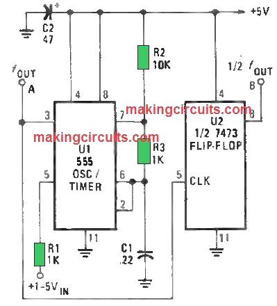
As a result, the output-waveform symmetry gets affected as the frequency fluctuates from one end to the other. At the peak frequency, the waveform is shared. However, as the frequency dips the output of the circuit switches into a thin pulse.

Say you need a symmetrical waveform, you just need to introduce a second IC, U2 (half of a 7473P dual TTL J-K flip-flop) to the oscillator circuit. But there’s a catch. U2’s signal frequency output is one-half of what is entering. To compensate the discrepancy, you just need to two-fold the frequency of the voltage controlled oscillator (VCO).

Simple VCO using LM3900

Through the use of the LM 3900N quad opamp, an easy convenient battery controlled VCO could be built quite at low cost.

A1 forms an integrator, the ramp rate based on the voltage Vi and capacitor C. This ramp is fed to a Schmidt trigger which switches at around 5V8, creating A1 ramp down, producing a triangular wave of around OV85.

fig1 36

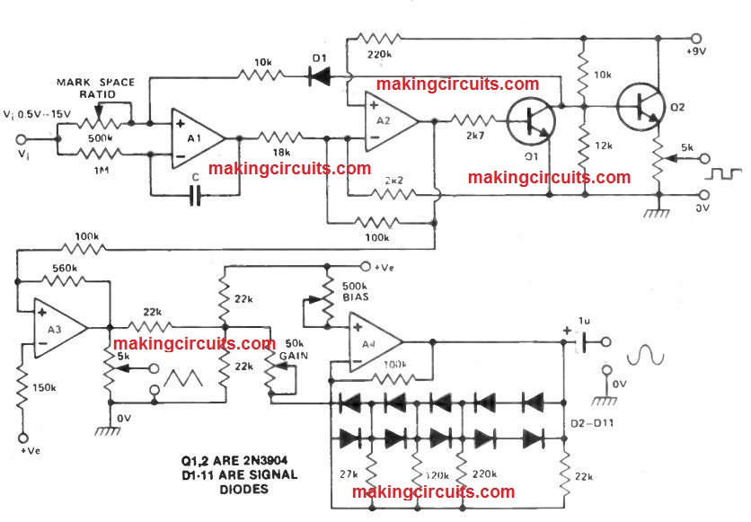
The Schmidt trigger supplies a transistor switch and an emitter follower.

The triangular wave is then fed to A3 which will act as an inverting amplifier, and the output is fed to A4 which can be an hugh integrator set at a pseudo ground of 4V5.

The bias and gain pots of the voltage controlled oscillator circuit needs to be modified to achieve the ideal sine waveform. Vi could be any kind of positive voltage from +0.5 to + 15.0 V, providing an frequency range of around 1:100.

Capacitor C could be any value from 1 On to 47n and the outputs possess a low distortion around about 20 kHz.

You'll also like:

  • 1.  Make these Simple Colpitts Oscillator Circuits
  • 2.  How to Make a Wien-Bridge oscillator Circuit (Sinewave Oscillator)
  • 3.  Motor Boat Sound Generator Circuit
  • 4.  12 Best Oscillator Circuits Explained
  • 5.  Simple Oscillator Circuits
  • 6.  Low Voltage Crystal Oscillator Circuit

About Admin

Hey friends, Thanks a bunch for stopping by this site! I am an engineer with a Bachelor of Engineering in Electronics and Telecommunication. One of my passions is gathering information from all sorts of electronics books and tutorials. I then take that information and compile it into a language that is super easy to understand. My goal is to make those complex electronics circuit concepts and technical terms much more accessible for all the new and budding electronics engineers out there. I can also design customized circuit diagrams as required by the users.
If you have any questions related to this field, please do not hesitate to drop a comment! I am always here and ready to help you out with any queries you might have. I cannot wait to hear from you!

Reader Interactions

Leave a Reply Cancel reply

Your email address will not be published. Required fields are marked *

Primary Sidebar

Categories

  • 3 Phase (4)
  • 8051 Microcontroller (1)
  • Arduino (11)
  • Audio and Amplifier (102)
  • Automation (8)
  • Battery Chargers (64)
  • Bicycle Projects (4)
  • Car and Motorcycle Projects (39)
  • Datasheets (10)
  • DIY Projects (5)
  • Electrical (15)
  • Free Energy (6)
  • Games Projects (2)
  • High Voltage (14)
  • Hobby Projects (30)
  • Household Circuits (2)
  • IC 555 Circuits (5)
  • Ignition Circuits (2)
  • Indicators (50)
  • Infrared (6)
  • Inverter Circuits (29)
  • Lights and Lamps (97)
  • Medical (8)
  • Meter and Tester Circuits (38)
  • Motor Driver (17)
  • New Circuits (56)
  • Oscillators (30)
  • Pets and Pests (5)
  • Power supply (80)
  • Protection Circuits (25)
  • PWM (9)
  • Remote Control (20)
  • Security and Alarm Circuit (48)
  • Sensors and Detectors (66)
  • Signal Processor (23)
  • Solar Controller Circuits (62)
  • SSR (3)
  • Temperature Controller (20)
  • Timer (25)
  • Transformerless (7)
  • Transmitters (12)
  • Tutorials (45)
  • UPS (2)
  • Voltage Regulators (57)
  • Water Sensor and Controller (29)
  • Home
  • Privacy Policy
  • Contact
  • Disclaimer
  • Copyright

© 2025 · Making Easy Circuits