Everyone knows that for working heavy electrical loads three phase power or AC is needed to be able to produce the working economical and viable. But yet this demands the existence of all the three stages at all situations. If any of the levels fail, may cause devastating effects to the linked systems. The following article provides a good alternative for tackling the above problems.
As mentioned above, a three phase load for example an industrial heavy motor will need the occurrence of all the three input AC mains phases for efficient and right procedures.
If there is certainly any conflict with the existence of the input phases, the motor may well commence working under greatly demanding and irregular problems.
This could result in large current intake, warming of the winding and eventually burning of the motor parts.
The circuit of a single phasing preventor demonstrated below may be efficiently useful for removing all sorts of unwanted outcomes which may derive from an unusual three stage problems.
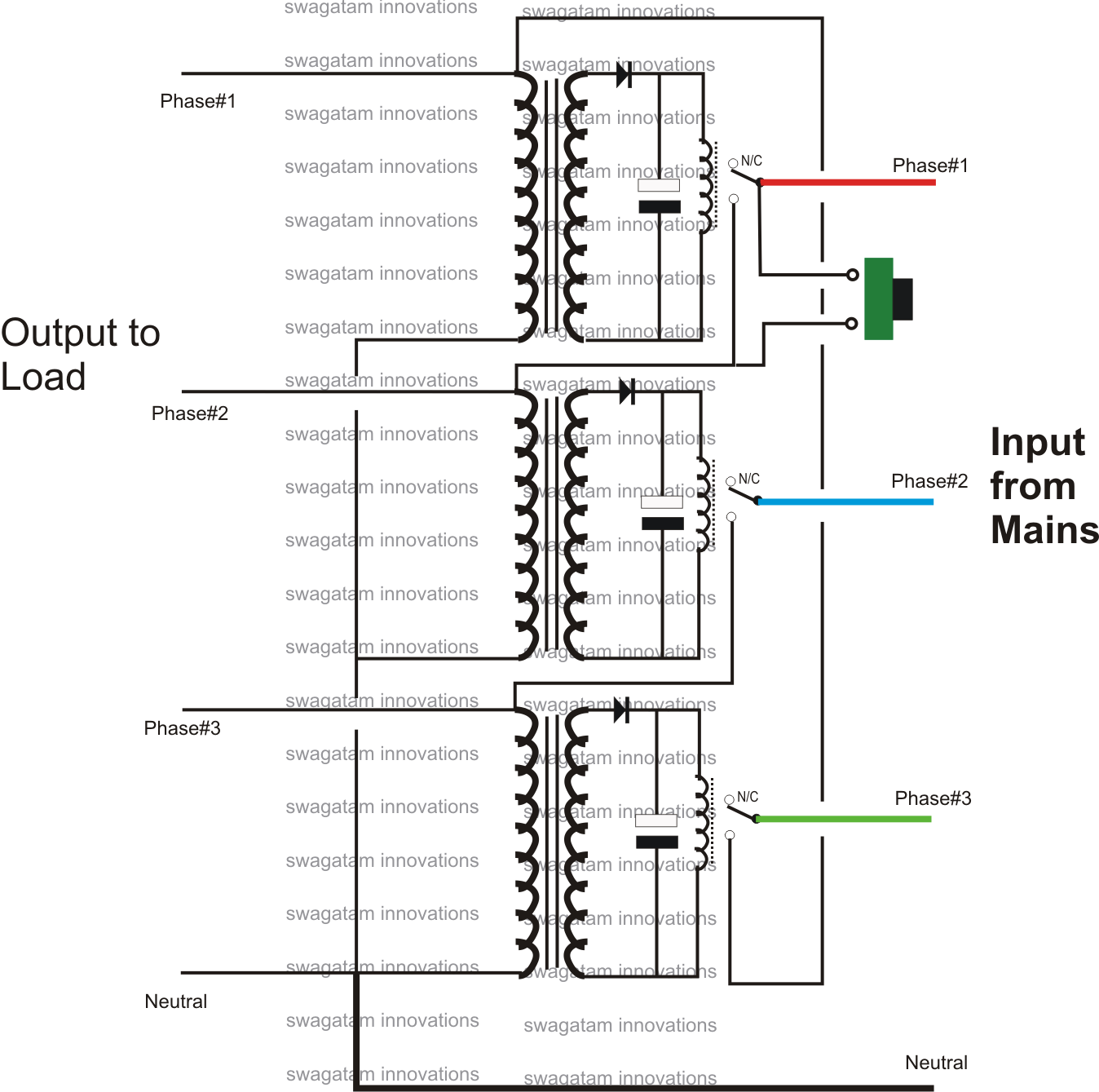
In the diagram we are able to notice the utilization of three transformer/relay driver stages.
The transformers could be the regular step-down types, graded properly for changing the associated relays.
Certainly one of the input primary terminals of all the transformers are created normal and associated with the basic line.
While the other terminals of each transformer are attached to the specific first, second and the third phases of the input mains.
In spite of this the above connections are carried out skillfully via the relay N/O contacts of the following relay assemblies for applying the needed single phasing prevention.
At first when the set-up is built-in with the the three phases as per the presented connections, the phases are remain cut off from the output load, simply because the relay contacts are all open.
On pressing the provided push button, the specific step in the line is permitted to achieve the second or the middle transformer primary winding.
The middle transformer immediately works its own relay, whose contacts exactly like the above relay attaches the second respective phase with the primary of the bottom transformer, which lastly functions its relay running the top transformer.
As soon as this occurs the whole method gets latched via the N/O contacts of the relays such that now even if the push button is introduced the system proceeds and maintains the voltages across the outputs and to the transformers.
Right now guess if any of the stages turn out to be low or fails, the specific transformer in line instantaneously deactivates its relay and the whole process of relays break down in series, instantly avoiding and disconnecting the output loads.
Hence the process efficiently stops the loads from functioning under the loss of any of the levels rendering it sure nothing goes out in fumes.
The circuit was developed solely by me, I assume so, if it's previously been found out please supply me with the link:
Another simple single phase preventor circuit can be seen the following diagram:
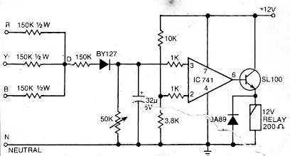
As can be seen in the design, the voltages from all the 3 phase are fed to the non-inverting pin#3 of the opamp, via a rectifying diode, so that a DC becomes available at this pin of the IC.
Pin#2 which is the inverting input of the opamp is held at some constant reference level through the voltage divider network using a 3k3 and a 10k resistor.
As long as all the 3 phases are present, the sum of their phases produce a zero potential at pin#3 of the IC, this happens since we all know that sum of the phases when joined end up producing a zero potential.
Therefore pin#3 is held at 0V, which tends to be lower than the pin#2 of the IC, resulting in a 0V at pin#6 of the IC which keeps the relay switched OFF.
However in a case where any one or two phases are absent allows the pin#3 potential to climb a much higher level than pin#2, resulting in a high at pin6 of the IC, the relay responds and toggles ON, shifting contacts to the N/O position.
Now since the relay contacts become responsible for disconnecting or connecting the load with the 3 phase supply, due to an absence or a missing phase. Therefore it becomes imperative to use a 3 contact relay, through which the load may be enabled with the 3 phases for its operation.
With such connection whenever the relay toggles, it either connects the lad or disconnects the load from all the 3 phases depending on whether the 3 phase is good or bad, thus implementing the intended 3 phase prevention for the load.
which gauge of wire has max carring current of 208amps i do not have the chart
you can search for “wire Current Calculator” and estimate the value there…
thanks sir for ur responses i am using it on a 3phase motor.but am also stil studing the 3phase inverter for running it thanks will be updating you how fur i will have reached have ablessed day
you are most welcome olupot…wish you all the best
thanks sir for ur answers am using for running my motor have a blessed day sir
it’s my pleasure!
thanks alot sir for ur responses
i need some answers regarding the first circuit i want to use it on a 3phase motor rated at 380volts so what wil be the voltage at each phase thanks
Hi olupot, you can try it……I think each phase is supposed to be 380V right?
Dear Sir
I like single phase preventer diagram.
Please send the PCB Diagram.
Gavade, if possible i’ll try to update it soon
Sir we have three phase a/c every time supply gone a/c is not working after change the phase than a/c is working what is any solution automatic change the phase
Kuldeep, phase cannot be the issue for stopping the AC from working, there could be something else causing the issue… you will have to consult an AC expert for this..
Here we have to use transformer or not how we will.give the supply to these terminals plz help
for the second circuit you can use a small 12v transformerless power supply circuit
Plzz I make simple phasing preventor …
Give me a wiring diagram of this project
I’ll update an easier design soon in the article for you
Sir.. please send me a single phase preventer using optocoupler diagram..
3 phase outlets do not have neutral line…please check the diagram and do the needful…
ok I’ll check it…by the way the neutral could be in the form of an earthing