• Skip to main content
  • Skip to primary sidebar

Making Easy Circuits

Learn and build electronic circuits

You are here: Home / DIY Projects / 10 Step Relay Selector Switch Circuit

10 Step Relay Selector Switch Circuit

Last Updated on August 26, 2013 by Admin Leave a Comment

The article describes a straightforward yet practical circuit for a 10-step selector switch that may be controlled with a single push-to-ON button. The circuit is utilized as a three-step, single push motor speed controller unit in the schematic layout that follows.

This circuit was requested by one of the avid followers of this blog, as given below:

Scientific Details

Hi, sir. I hope you have a pleasant day. Would you kindly design a circuit to control the speed of my DC motor using only one switch (a push button)? It should be set to low on the first push, medium on the second, and high on the third. My 12-volt relay, which has three relays for low, medium, and high settings, will be connected to the output. My DC motor, which includes a rheostat for speed control, will thereafter receive the relay's output. I'm going to utilize this for the air conditioning system in my car. Thank you, and keep up the fantastic blog work!

Circuit Diagram


electronicselectorswitchcircuit

4017

Circuit Description

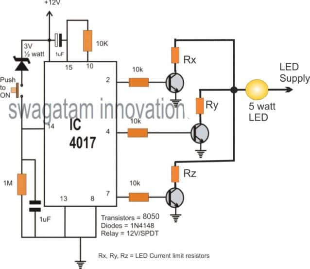
When high/low alternate logic switching occurs at pin #14, the IC 4017, a Johnson decade counter IC with 10 decoded outputs, is intended to provide sequential logic high outputs.

The change in the position high logic cycles are generated across the IC's output pinouts from pin #3 to pin #11 when pin #14 is activated or flipped employing a push-button switch.

shortly as the logic sequence hits pin #7 of the IC, the IC is reset back to the initial pinout because just three outputs are needed in the schematic that is displayed for executing three relay-based switches.

You may set up the transistor relay driver stages throughout all ten of the IC's output pins whenever you wish to create a 10 relay functionality.

The circuit for Applications:

As seen below, the aforementioned idea may be used as a three-step LED brightness controller with just one push button:

push button led brightness control circuit

You'll also like:

  • 1.  Make this Two Tone Alarm Circuit using NAND Gates
  • 2.  Practical Circuits using LM338 IC
  • 3.  Make an Electronic Candle Circuit with Puff OFF
  • 4.  Transformerless 220V Lamp Chaser Circuits for Festival Decorations

About Admin

Hey friends, Thanks a bunch for stopping by this site! I am an engineer with a Bachelor of Engineering in Electronics and Telecommunication. One of my passions is gathering information from all sorts of electronics books and tutorials. I then take that information and compile it into a language that is super easy to understand. My goal is to make those complex electronics circuit concepts and technical terms much more accessible for all the new and budding electronics engineers out there. I can also design customized circuit diagrams as required by the users.
If you have any questions related to this field, please do not hesitate to drop a comment! I am always here and ready to help you out with any queries you might have. I cannot wait to hear from you!

Reader Interactions

Leave a Reply Cancel reply

Your email address will not be published. Required fields are marked *

Primary Sidebar

Categories

  • 3 Phase (4)
  • 8051 Microcontroller (1)
  • Arduino (11)
  • Audio and Amplifier (102)
  • Automation (8)
  • Battery Chargers (64)
  • Bicycle Projects (4)
  • Car and Motorcycle Projects (39)
  • Datasheets (10)
  • DIY Projects (5)
  • Electrical (15)
  • Free Energy (6)
  • Games Projects (2)
  • High Voltage (14)
  • Hobby Projects (30)
  • Household Circuits (2)
  • IC 555 Circuits (4)
  • Ignition Circuits (2)
  • Indicators (50)
  • Infrared (6)
  • Inverter Circuits (29)
  • Lights and Lamps (97)
  • Medical (8)
  • Meter and Tester Circuits (38)
  • Motor Driver (17)
  • New Circuits (56)
  • Oscillators (30)
  • Pets and Pests (5)
  • Power supply (81)
  • Protection Circuits (25)
  • PWM (8)
  • Remote Control (20)
  • Security and Alarm Circuit (48)
  • Sensors and Detectors (66)
  • Signal Processor (23)
  • Solar Controller Circuits (61)
  • SSR (3)
  • Temperature Controller (20)
  • Timer (25)
  • Transformerless (7)
  • Transmitters (12)
  • Tutorials (45)
  • UPS (2)
  • Voltage Regulators (57)
  • Water Sensor and Controller (29)
  • Home
  • Privacy Policy
  • Contact
  • Disclaimer
  • Copyright

© 2025 · Making Easy Circuits