• Skip to main content
  • Skip to primary sidebar

Making Easy Circuits

Learn and build electronic circuits

You are here: Home / Timer / Snooze Delay Timer Circuit

Snooze Delay Timer Circuit

Last Updated on September 22, 2021 by Admin Leave a Comment

You can switch ON the "Snooze" function by pressing the S1 button and add a desired delay to the connected alarm

The alarm is muted for some time so that you can sleep for another few minutes.

In this article we learn how to make a simple Snooze Delay Timer Circuit using very ordinary components.

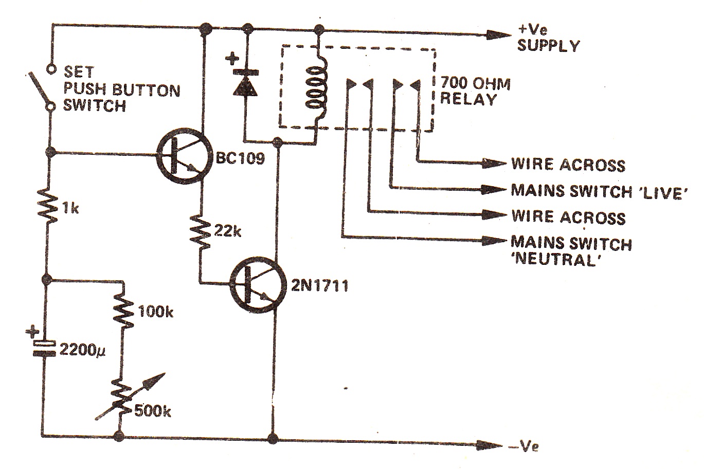
When the Set switch is depressed the large electrolytic capacitor is charged via the limiting resistor (lk).

How the Circuit Works

This charge causes the BC109 to conduct which supplies enough base current to switch on the 2N1711 space and operate the relay.

The relay contacts are wired in parallel with the mains switch so that if the mains switch is now turned off, the equipment will continue.

The supply·voltage is taken from the equipment in which the unit is fitted and will determine the choice of` relay.

The maximum delay being 1.75 hours.

Snooze Delay Timer Circuit

snooze timer delay circuit

You'll also like:

  • 1.  Simple Relay Delay Timer Circuits using IC 4001
  • 2.  Making Delay Timers using NOT gates IC 4049
  • 3.  Accurate 24 Hour Timer Circuit
  • 4.  IC 4060 based 2-step Programmable Timer Circuit
  • 5.  Dark Room Timer Circuit
  • 6.  Simple 1 minute to 60 minutes Timer Circuit using IC 4011

Tagged With: Timer

About Admin

Hey friends, Thanks a bunch for stopping by this site! I am an engineer with a Bachelor of Engineering in Electronics and Telecommunication. One of my passions is gathering information from all sorts of electronics books and tutorials. I then take that information and compile it into a language that is super easy to understand. My goal is to make those complex electronics circuit concepts and technical terms much more accessible for all the new and budding electronics engineers out there. I can also design customized circuit diagrams as required by the users.
If you have any questions related to this field, please do not hesitate to drop a comment! I am always here and ready to help you out with any queries you might have. I cannot wait to hear from you!

Reader Interactions

Leave a Reply Cancel reply

Your email address will not be published. Required fields are marked *

Primary Sidebar

Categories

  • 3 Phase (4)
  • 8051 Microcontroller (1)
  • Arduino (11)
  • Audio and Amplifier (102)
  • Automation (8)
  • Battery Chargers (64)
  • Bicycle Projects (4)
  • Car and Motorcycle Projects (39)
  • Datasheets (10)
  • DIY Projects (5)
  • Electrical (15)
  • Free Energy (6)
  • Games Projects (2)
  • High Voltage (14)
  • Hobby Projects (30)
  • Household Circuits (2)
  • IC 555 Circuits (5)
  • Ignition Circuits (2)
  • Indicators (50)
  • Infrared (6)
  • Inverter Circuits (29)
  • Lights and Lamps (97)
  • Medical (8)
  • Meter and Tester Circuits (38)
  • Motor Driver (17)
  • New Circuits (56)
  • Oscillators (30)
  • Pets and Pests (5)
  • Power supply (80)
  • Protection Circuits (25)
  • PWM (9)
  • Remote Control (20)
  • Security and Alarm Circuit (48)
  • Sensors and Detectors (66)
  • Signal Processor (23)
  • Solar Controller Circuits (62)
  • SSR (3)
  • Temperature Controller (20)
  • Timer (25)
  • Transformerless (7)
  • Transmitters (12)
  • Tutorials (45)
  • UPS (2)
  • Voltage Regulators (57)
  • Water Sensor and Controller (29)
  • Home
  • Privacy Policy
  • Contact
  • Disclaimer
  • Copyright

© 2025 · Making Easy Circuits