Hey there, I’m excited to share with you how we can create a straightforward circuit that tests the moisture levels in soil or mud. All we need is a single op-amp and a handful of passive components. Let’s explore the details together in this article!
The Purpose of Our Circuit
After water and sunlight, I believe we cant overlook how vital the earth, or soil really is. It’s one of the most precious gifts our planet has given us. Without it life as we know it wouldn’t even be possible!
Soil is responsible for producing plants and those plants in turn provide us with food. But here’s the catch: for plants to thrive, they need well-watered soil. In other words crops just can’t survive without the right amount of water in the ground where they grow.
Thats why I find it super important to figure out the right soil moisture levels if we want to cultivate healthy crops while also being smart about our water usage.
Who Can Use This Tester?
What’s great about this simple soil moisture tester circuit is that it’s designed for anyone like you and me who wants to check or keep an eye on the moisture levels in a specific area of land.
This way we can ensure that our plants get just the right amount of water whether we’re doing it manually or letting the circuit handle it automatically.
So we’ve got options! This circuit not only allows us to measure soil moisture but can also be transformed into an automatic moisture controller. All I need to do is connect a motor pump to the relay contacts in the circuit.
Now let’s take a closer look at how this circuit is designed to operate.
Overview of the Circuit Design
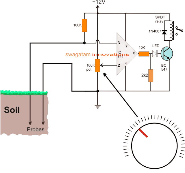
So if I take a look at the circuit we have up there it’s pretty neat because it uses just one single IC 741 op-amp comparator to perform the testing function I need.
How It Works
Now let’s talk about the specifics. The non-inverting input of the op-amp which is pin 3 serves as my main sensor probe. This probe is compared to another probe that’s connected to the ground.
What’s really interesting is how moisture levels in the soil affect resistance. When there’s more moisture in the soil I notice that the resistance is lower and as the moisture decreases the resistance goes up. So basically wet soil has a much lower resistance compared to dry soil.
Probing Soil Resistance
In this design I’m taking advantage of that principle by using these probes to measure the soil resistance between pin 3 and ground on my IC 741 comparator.
This soil resistance acts like a potential divider along with a 100K resistor that’s hooked up between the positive supply line and pin 3 of the IC. The potential difference that develops here in response to the moisture level in the soil is then compared with what’s happening at pin 2.
The voltage at pin 2 is set by adjusting a 100K potentiometer (pot). This pot helps me determine or verify just how much moisture is actually present in the soil.
Output Behavior
Now here’s where it gets a bit more technical: if the moisture in the soil creates a lower resistance at pin 3 than what I’ve set at pin 2 then the output at pin 6 drops low.
This means that when the soil is relatively wet I’ll see zero volts coming out of the op-amp. On the flip side if the soil becomes drier and thus develops a higher resistance then I’ll get a positive output from the op-amp. This positive output triggers a connected transistor and activates a relay.
To put it simply as long as the moisture level in the soil stays above that threshold I set with my pot at pin 2 both the output of the op-amp and the relay will remain OFF. Conversely when the soil gets dry enough to drop below that threshold it switches ON. So essentially wet soil keeps that relay switched OFF while dry soil turns it ON.
LED Indicator
Oh and there’s also an LED involved! It complements what’s happening with the relay by lighting up whenever the soil is drier than my desired level.
Calibration Process
Now before I start using this setup I need to calibrate that pot properly. I can do this by turning the dial and marking various points based on predetermined moisture content from some sample soil I’ve collected in a container.
Once I’ve got that calibration done I can easily check any other soil by sticking those probes into it and adjusting that pot until I see a high output which means LED ON.
Using This Circuit as a Soil Moisture Controller
So here’s how I can actually use this circuit as a soil moisture controller: once I set my pot to my desired value whenever the moisture level in my soil drops below that setting bam! The relay gets activated right away.
When it switches ON it connects its normally open (N/O) contacts. I could wire these contacts to control a water pump and its power supply in series. So every time that relay clicks ON my motor pump starts working and begins supplying water to my soil until it reaches that optimal moisture level I’m aiming for.
When everything is back to normal and the op-amp detects that ideal condition again it quickly flips back to zero logic at its output. This action turns OFF both the relay and motor stopping any water flow.
And guess what? This whole process keeps repeating itself! It continuously checks on soil moisture levels and waters accordingly all without needing any manual help from me!
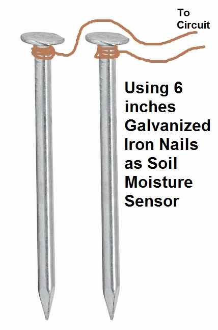
Using Iron Nails as Probes
For my sensor probes I can keep it simple by using a pair of good quality galvanized iron nails about six inches long should do just fine! I just solder some sensor wires from my op-amp circuit onto those nails and push them down into the soil aiming for at least five inches deep.
Just make sure those probes aren’t spaced more than three inches apart while they’re in there!
Exploring a Moisture Sensor with Copper and Zinc Mesh
So I recently came across a really intriguing idea suggested by one of the dedicated readers of this blog, a guy named Phil. He’s got this concept that I think is pretty fascinating and I wanted to share it with you all.
Phil mentioned that he’s been toying with what he believes might be an impossible circuit but he’s eager to get some feedback on it.
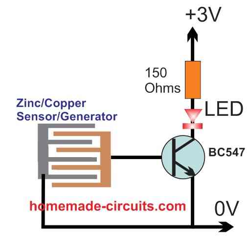
Now I’m sure many of you are familiar with a basic moisture tester. These nifty devices typically use two different metals, usually copper and zinc. When these metals come into contact with moisture—like water—they generate a tiny electrical current. Thats the foundation of Phil's question.
He’s curious if there’s any way to create a circuit or device that could be powered by something like a 3.7V lithium-ion battery or even a simple 1.5V AAA battery.
The catch is that this device would remain in the "off" position until it detects moisture through two leads made of those dissimilar metals.
Once moisture is sensed, it would power up and light up a low-voltage LED to indicate that there’s moisture present across those two leads.
Oh and here’s the kicker..... it should be designed in such a way that it wouldn’t deliver any kind of shock if it came into contact with sensitive skin.
I think this idea has some real potential! What do you all think?
Using Soil Moisture Sensor to Control a Motor Pump
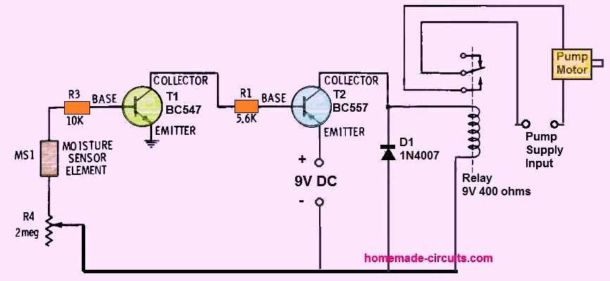
OK, so I wanted to share some thoughts on how we can take that previous circuit we built using a single BC547 and give it a cool upgrade to create a soil moisture controller circuit that works with a motor pump.
So let’s start with the moisture sensor. We can use the same setup as in the earlier diagram which features those zinc and copper tracks positioned really close together. It’s a simple yet effective way to detect moisture!
Now here’s how it works: when the soil is dry and there’s no moisture present, there’s no voltage being sent to the base of the BC547 transistor. This means that both transistors in the circuit remain switched OFF which keeps the relay in the OFF position as well.
Since our motor pump is connected to the normally closed (N/C) contacts of the relay, it stays ON allowing water to flow into the soil. Pretty perfect, right?
But here’s where it gets interesting, when moisture or even tiny water droplets are detected by our moisture sensing element, a small electrical potential is generated across those sensor terminals. This little voltage is just enough to turn ON the BC547 transistor which then causes the BC557 transistor to switch ON as well.
Once the BC557 is activated, it turns OFF the relay contacts that were previously keeping everything running because of that dry sensor detection. As a result the relay cuts power to the motor pump, stopping it from pumping water. The pump will stay OFF as long as there’s moisture detected by the sensor.
For optimal performance you can insert this moisture sensor deep into the soil where you want to monitor and control moisture levels with that motor pump. And if you want to tweak how sensitive your moisture sensor is, you can use pot R4 to adjust its sensitivity.
I think this setup could really help manage soil moisture effectively! What do you all think?
Leave a Reply