• Skip to main content
  • Skip to primary sidebar

Making Easy Circuits

Learn and build electronic circuits

You are here: Home / Voltage Regulators / Solid State 220V to 110V Converter Circuit

Solid State 220V to 110V Converter Circuit

Last Updated on February 16, 2019 by admin Leave a Comment

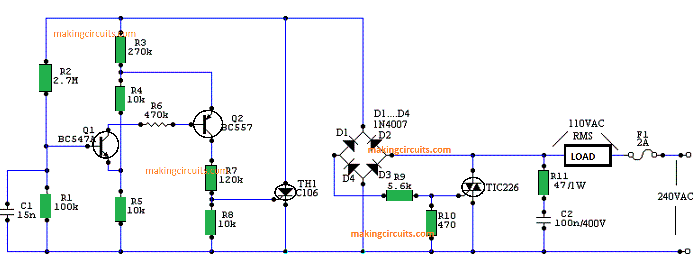
Through this functional circuit it is possible to acquire 120 VAC RMS from 240 VAC. Typically, in these circumstances precisely what is employed is a huge transformer for the step down operation, however in this situation we don't use anything but some solid state components to obtain identical benefits. It is essential to clarify that our circuit works extremely well with resistive loads only (water heaters, resistances bulbs, aquarium heaters, etc.), meaning that inductive loads such as motors, blenders, shiners and others, cannot be hooked up simply because it might quite possibly degrade the parts used.

The voltage stepping down is implemented, as a result of a tiny phase angle control circuit, that transmits a couple of trigger signals to the Triac TH2 for every single cycle of the input voltage waveform. The goal is to slice an area of the wave so that the specified voltage is acquired while executing the RMS calculations. For 120 Volts, the phase angle in which the Triac has to move the voltage is approximately 110 °.

The output voltage needs to be assessed with a TRUE RMS voltmeter with the load hooked up. The reason being the waveform is not completely senosoidal. If this voltage is not desirable, the value of resistance R2 could be varied until the instrument exhibits what we should actually need.

If you wish to regulate greater power loads, just replace the Triac for a value that will facilitate more current and put in a heat sink simultaneously.
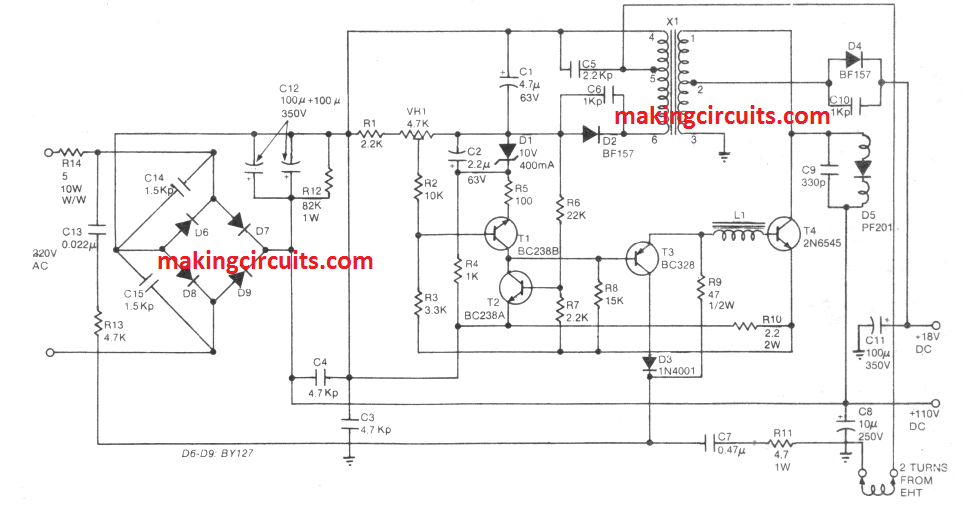
220V to 110V converter circuit

SMPS 110V Converter

In this section we learn about an 110V converter using SMPS mode. The design is based on flyback principle. You will two outputs from this converter circuits, 18V and 110V from a 220V input AC mains. The circuits was originally designed for TV sets, but it can be also used for operating any 110V device.

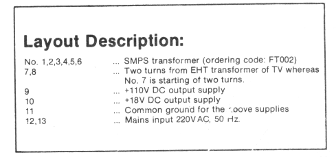
You can remove and ignore the "2 turns from EHT.

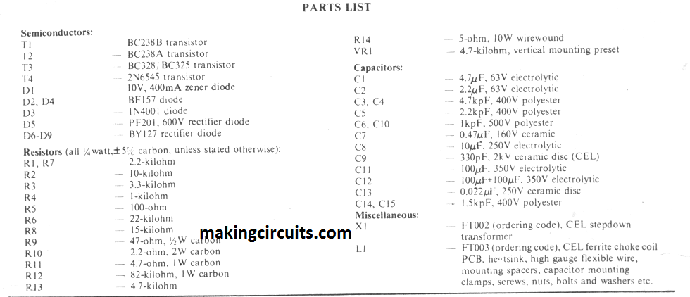
SMPS Transformer Details

110V converter transformer details ferrite core

You'll also like:

  • 1.  3V to 110/220V Converter Circuit
  • 2.  Voltage Stepper Circuit or Voltage Booster Circuit
  • 3.  High Power Triac Dimmer Circuit for 1000 watt Loads
  • 4.  Mains 220V/120V Short Circuit Breaker Protector
  • 5.  Light Dimmer Circuit
  • 6.  Zero Crossing Detector Circuit

About admin

Reader Interactions

Leave a Reply Cancel reply

Your email address will not be published. Required fields are marked *

Primary Sidebar

Categories

  • 3 Phase (4)
  • 8051 Microcontroller (1)
  • Alarm (37)
  • Amplifier (41)
  • Amusement (32)
  • Arduino (9)
  • Audio (50)
  • Automation (5)
  • Battery Chargers (47)
  • Bicycle Projects (2)
  • Bluetooth (3)
  • Capacitor (2)
  • Car Electronics (24)
  • Cellphone (7)
  • Datasheets (8)
  • Detector (32)
  • Electrical (15)
  • Emergency Light (8)
  • Free Energy (3)
  • Gadgets (10)
  • High Voltage (13)
  • Hobby Projects (30)
  • IC 555 Circuits (5)
  • Ignition Circuits (2)
  • Indicators (46)
  • Infrared (6)
  • Inverter (23)
  • LED Projects (49)
  • Light effect (19)
  • Medical (7)
  • Meter and Tester Circuits (32)
  • Motor Driver (16)
  • Motorcycle Projects (2)
  • New Circuits (25)
  • Oscillators (26)
  • Power supply (40)
  • Protection Circuits (26)
  • PWM (9)
  • Remote Control (16)
  • Security Circuit (14)
  • Sensors (34)
  • Signal Processor (23)
  • SMPS (12)
  • Solar (43)
  • SSR (3)
  • Temperature Controller (18)
  • Timer (23)
  • Transformerless (9)
  • Transmitters (11)
  • Tutorials (36)
  • UPS (2)
  • Voltage Regulators (49)
  • Water Control (8)
  • Water Sensor (13)
  • Home
  • Privacy Policy
  • Contact
  • Disclaimer
  • Copyright

© 2023 · Making Easy Circuits