So in this post we are going to see one kind of improved transformerless power supply circuit design, that is having two important stages. First part is a good regulated DC output stage and second part is a relay driver stage which is getting triggered through one outside positive pulse. That full idea was actually suggested to us by Mr. Alexandar.
Technical Request from Mr. Alexandar
Alexandar: Good day Sir, I am having one problem with one circuit, that is supposed to convert one AC 110V power supply into 220V or even 250V AC. But I am not able to do that conversion properly.
Your blog site and those powerful circuits you are posting there are really mind blowing. Honestly Sir, you are one Electro Man! My interest is increasing more and more every time I am visiting your site. That interest only is making me ask you for help to solve my problem.
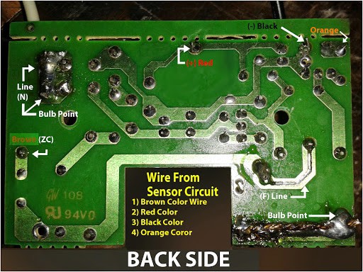
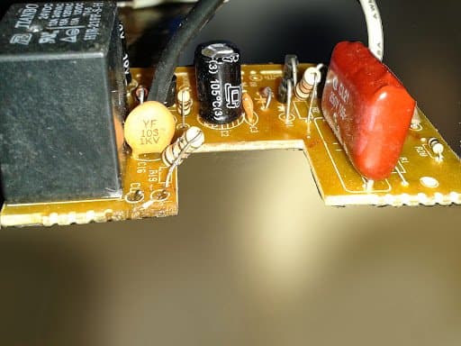
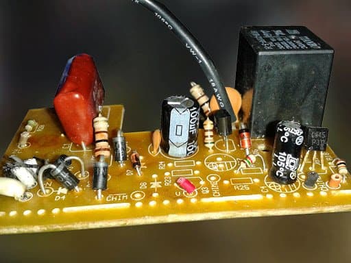
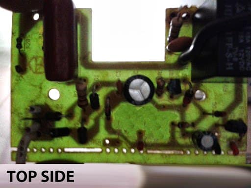
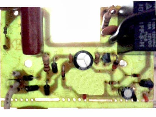
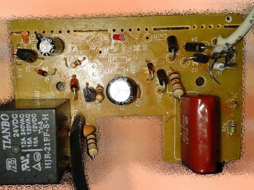
So Sir, I want to send you few pictures of that circuit which I am trying to modify from 110V AC to 220V or 250V AC input from main line.
I am waiting for your answer. Can you please tell me simply whether I just need to change only the 105-250V capacitor and those two resistors which are 100kΩ and 100Ω or is there anything more I must change?
But honestly I am feeling confused what is the correct thing to do for converting to 220V or 250V. Just for your info Sir, I already changed the 200 watt halogen bulb also.
I have used two square size LED pieces (one for each bulb head), and also I have added external 5V mobile charger adapter as power source for my LEDs, which I connected with RL1 relay.
My Immediate Response
Me: Can you tell me clearly what exactly you are trying to make or build?
Alexandar: I am not building anything new Sir. I just want to convert my existing 110V motion sensor device to work with 220V AC. Thats all.
But I do not know what is the correct method to do that. So I really need your help Sir. It is having one transformerless power circuit board, that is why I am stuck.
Circuit Diagram

Circuit Working Explanation
So now before we jump into how to modify that circuit for 220V use, first let us understand how this transformerless power supply is working. This one is little advanced design because it is also having one relay triggering stage inside it.
If we see the below diagram carefully, we can divide the whole circuit into different sections like this:
- C1 is one high voltage capacitor, which is used to drop the main AC current to low safe level that the circuit can handle.
- D3, D5, D6, D7 – these four diodes are forming one standard bridge rectifier section.
- C2, C4 are filter capacitors. These are used for removing all the ripples and spikes from the rectified DC.
- Q2 is used in emitter follower mode. Its base is fixed to 24V using the zener diode D9 and resistor R7.
Because Q2 is in emitter follower mode, so its emitter voltage will also become same as its base voltage which is 24V. Also the current at emitter will be equal to base current + collector current.
Now this +24V from Q2 emitter is going directly to the 24V relay coil through Q1 transistor. And this Q1 is triggered using some external positive pulse coming from orange wire through R10 resistor. When that pulse comes, Q1 switches ON and relay turns ON.
Then we can also see one more small section – R8 and D8 – connected with emitter of Q2. This part is creating a 5V stabilized supply, maybe for some special small load which is connected across that RED wire.
R5 is included for controlling surge current during switch ON. R6 is used for discharging C1 capacitor after unplugging the circuit from mains, for safety.
How to Modify for 220V Operation
Now because Mr. Alexandar wants to make this same circuit work with 220V to 250V AC also, we have to check what components need to be upgraded.
But if we see carefully, actually everything in the circuit is already quite suitable for wide range voltage. It is almost okay to handle input from 110V to 300V. Only one part we must change – that is C1.
So we should change C1 to 105/400V rating. That means 1uF/ 400V capacitor.
Also maybe R7 should be adjusted a bit – maybe higher wattage or slightly different value to suit higher input current.
We should also increase R6 value to 1MΩ for better discharging effect of C1 when used with 220V.
Other than these, everything else in this circuit looks perfect and well designed. So it can work nicely even at 220V or 250V without much issue.


Hello Sir,
I have a couple of questions regarding your above schematic:
– is C2 really a 473F (Farad) capacitor? Can find one to buy. Do you have a link/part# ?
– same with C4, C6 = 100mF (100000 µF).
I see C5=103F. Is it really 103F (farad), or – I’m guessing here – you use a personal notation for capacitors, where one should (sometimes) ignore the ‘F’ and, in this case, read the value as 103 pF, or 10nF ?
Thanks!
Sorry for the confusion Johnny,
Please ignore the F.
473F refers to 47,000pF = 47nF
100mF = 100 microfarad or 100uF
103 = 10,000 pF = 10nF.