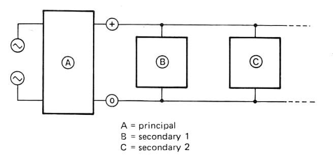
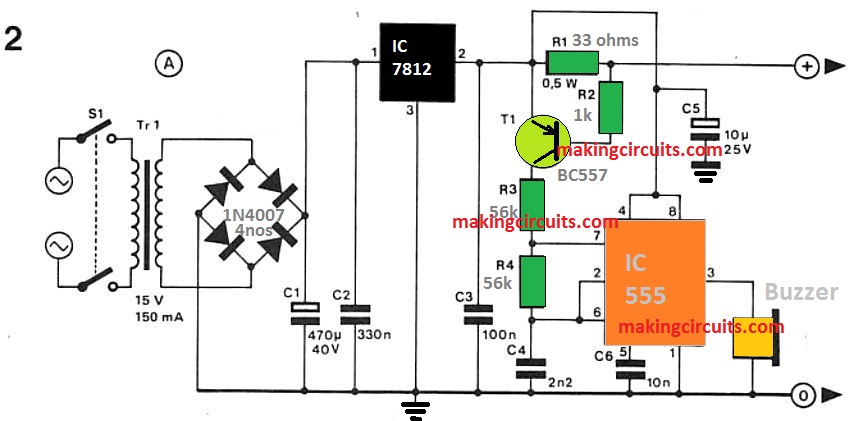
This temperature alarm circuit permits a concurrent checking of a maximum of four temperatures.
The individual detectors are attached to the main control unit by using a set of wires.

How the Circuit Works
When one of the sensors detects an unusually high or low temperature, an alarm sounds.


The setting of resistor R10 decides perhaps the alarm is triggered once the registered temperature goes up over a predetermined temperature setting or no matter if it sounds when it drops below the needed temperature.
When R10 is integrated amongst the positive supply line and the output of IC3, the alarm will probably be triggered once the assessed temperature surpasses that of the setting of P1.
In this particular scenario the output of IC3 drops as well as the detector begins to pull a current of about 20 mA.
Consequently the voltage around Rl turns into higher than 0.6 V leading to transistor Tl to perform and the alarm to sound.
This takes place simply because since the temperature increases the level of resistance of the NTC resistor (R9) reduces taking the inverting input of IC3 greater than the non-inverting input (voltagewise).
As a result leads to the output of the opamp to go minimal.
If resistor R10 is positioned amongst the output of IC2 and ground, the opposite occurs.
In this situation, since the temperature falls the resistance of R9 raises taking the inverting input of IC3 any longer were incorporated the quiescent current would certainly surpass that of the 'alarm current' and the design would not perform effectively.
In retrospect, the alarm current can not be enhanced as in that situation the output current of the opamp would be surpassed - along with negative effects! If an additional kind of alarm is essential, IC2 as well as its related parts can be disregarded and if the transistor enables you to handle a relay or some other comparable device.
The sensitivity of the circuit, quite simply the temperature at which the device functions, are adjustable by way of the preset potentiometer P1.
This could end up being beneficial much more negative compared to non-inverting input.
As a result, the output of the opamp goes high and a current of around 20 mA will flow by means of resistor R10.
This all over again leads to transistor Tl in the main control unit to perform and commence the alarm oscillator, 1C2.
The oscillator produces a tone of around 4 kHz which is then provided to the piezo-electric buzzer (Bz).
This particular fairly higher frequency was decided to address the resonant frequency of piezo elements because it is best with regards to the aural sensitivity curve.
As i have said earlier, the utmost amount of detector circuits that can be used is four.if to use a multi-turn preset to ensure that more precise options can be acquired.
Applications of this temperature alarm circuit will include a simple Fire alarm, the temperature control of two aquariums (each one requiring a optimum and a bare minimum detector) and a temperature regulator for central heating installations.
Schematics and images are not uploaded
Can you please check it now and confirm?