• Skip to main content
  • Skip to primary sidebar

Making Easy Circuits

Learn and build electronic circuits

You are here: Home / Meter and Tester Circuits / Transistor Current Gain Tester Circuit – hFE Tester

Transistor Current Gain Tester Circuit – hFE Tester

Last Updated on January 10, 2018 by Admin Leave a Comment

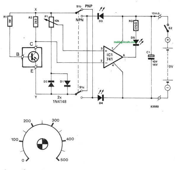
This hFE or transistor forward gain tester is intriguing due to its ease-of-use and because it allows the use of both PNP and NPN transistors to be assessed.

Additionally more the measuring becomes self-governing of the supply voltage of the tester. As the picture displays, the base current of the transistor under check moves through R1. lts base current Ig is therefore add up to the voltage drop along the collector resistor is hpg x lg x R2. P1 can be used to establish a reference voltage produced from voltage UXY — UD1 (or D2 for a PNP transistor).

Because of this the setting up of the potentiometer will be specifically relative to the hFE or the current gain of the transistor being tested and is also independent of source voltage.

The voltage throughout R2 and also the voltage fixed with P1 are investigated by IC1 that is attached as a comparator. Potentiometer P1 is at this point arranged such that the LED at the output of the op-amp merely lights or is just dimmed.

During this setting the voltage over the potentiometer add up to the voltage around R2. Switch S1 is applied to switch from NPN to PNP (or vice versa) by simply reversing “the polarity of voltage UXY. LEDs D3 and D4 in the source lines guarantee how the input voltages to be assessed are inside the common mode range of the op-amp utilized.


transistor hFE tester circuit, forward current gain tester

You'll also like:

  • 1.  Simple AC Mains Wattmeter Circuit
  • 2.  Vehicle Speedometer Circuit for Precise Speed Measurements
  • 3.  Noise Level Meter Circuit
  • 4.  FET Voltmeter Circuit
  • 5.  Simple Transistor Tester Circuit
  • 6.  Temperature Meter Circuit using RTD

About Admin

Hey friends, Thanks a bunch for stopping by this site! I am an engineer with a Bachelor of Engineering in Electronics and Telecommunication. One of my passions is gathering information from all sorts of electronics books and tutorials. I then take that information and compile it into a language that is super easy to understand. My goal is to make those complex electronics circuit concepts and technical terms much more accessible for all the new and budding electronics engineers out there. I can also design customized circuit diagrams as required by the users.
If you have any questions related to this field, please do not hesitate to drop a comment! I am always here and ready to help you out with any queries you might have. I cannot wait to hear from you!

Reader Interactions

Leave a Reply Cancel reply

Your email address will not be published. Required fields are marked *

Primary Sidebar

Categories

  • 3 Phase (4)
  • 8051 Microcontroller (1)
  • Arduino (11)
  • Audio and Amplifier (102)
  • Automation (8)
  • Battery Chargers (64)
  • Bicycle Projects (4)
  • Car and Motorcycle Projects (39)
  • Datasheets (10)
  • DIY Projects (5)
  • Electrical (15)
  • Free Energy (6)
  • Games Projects (2)
  • High Voltage (14)
  • Hobby Projects (30)
  • Household Circuits (2)
  • IC 555 Circuits (5)
  • Ignition Circuits (2)
  • Indicators (50)
  • Infrared (6)
  • Inverter Circuits (29)
  • Lights and Lamps (97)
  • Medical (8)
  • Meter and Tester Circuits (38)
  • Motor Driver (17)
  • New Circuits (56)
  • Oscillators (30)
  • Pets and Pests (5)
  • Power supply (80)
  • Protection Circuits (25)
  • PWM (9)
  • Remote Control (20)
  • Security and Alarm Circuit (48)
  • Sensors and Detectors (66)
  • Signal Processor (23)
  • Solar Controller Circuits (62)
  • SSR (3)
  • Temperature Controller (20)
  • Timer (25)
  • Transformerless (7)
  • Transmitters (12)
  • Tutorials (45)
  • UPS (2)
  • Voltage Regulators (57)
  • Water Sensor and Controller (29)
  • Home
  • Privacy Policy
  • Contact
  • Disclaimer
  • Copyright

© 2025 · Making Easy Circuits