Here we are making an electronic doorbell circuit that makes a dual-tone sound. So this thing is designed using the well-known IC 555. That IC 555 is something we see in many different timer circuits, but it is also a basic oscillator circuit.
Overview
In this circuit here we are using both of these functions, meaning the timer function and also the oscillator function of this IC.
So what happens now? When we press the given push button with our finger then this IC 555 starts oscillating at a particular frequency which means a specific tone will come out. But then when we take our finger off the button, then the frequency changes which means the sound also changes. So this IC keeps generating this new sound for some time. That timing depends on the RC time constant of the IC, meaning the combination of the resistor and capacitor connected to it decides for how long the sound will continue.
So in simple words when we press the doorbell button once then we hear two different tones one after the other. This sound is directly coming from a speaker, which is connected to pin#3 of the IC 555, and that pin is directly controlling the speaker’s output sound.
How This Circuit Works
Now let us see how this whole thing actually functions. If we check the diagram below, then we can break it down into some easy steps:
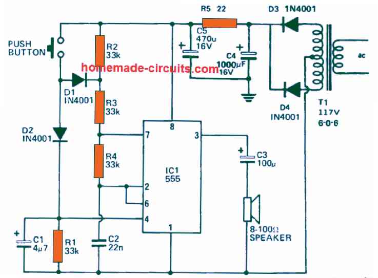
First when the circuit is powered on then this capacitor C2 starts charging up. It keeps collecting charge until it reaches the full supply voltage of +9V. But how does it charge? It takes power from the supply, and the charging path is through resistors R2, R3, and R4. So these resistors are basically allowing the capacitor to slowly reach the full voltage level.
But now because the upper end of this capacitor is connected with both pin#2 and pin#6 of this IC, that is why something interesting happens here.
So what happens now? As soon as the voltage across this capacitor starts reaching close to the 6V level then inside this IC, we have two comparators. Those comparators detect that this voltage is now crossing their threshold limit. Because of this, the IC 555 output at pin#3 suddenly goes low. But this is not the end, because this low output now forces the internal transistor inside this IC to switch on immediately.
Due to this transistor switching on, the pin#7 of the IC gets shorted to ground.
But since this pin#7 is also connected at a junction where we have the resistors R3, R4, and also this capacitor C2 now what happens is that this capacitor C2 begins discharging. It starts releasing its stored charge through resistor R4.
So during this discharging process, as soon as the voltage inside C2 falls down below 3V then again, this IC detects this situation and now its output suddenly goes high. When this happens, the internal transistor of this IC immediately switches OFF.
That means now, without wasting any time, this capacitor C2 starts charging again. But this time, it is charging through the resistors R2, R3, and R4 which are all connected in a particular way to allow this action.
This same sequence keeps happening again and again without stopping. Because of this continuous action, what we get is a triangular waveform across capacitor C2. This also results in a train of pulses appearing at the output pin#3 of this IC.
This pulse train that is coming out from pin#3 is further connected with a loudspeaker. But it is not connected directly. It is linked by means of capacitor C3.
Now why do we have capacitor C3 here? That is because this capacitor C3 makes sure that any DC voltage component coming out from pin#3 does not reach the loudspeaker. If this DC component reaches the loudspeaker, then there is a high chance that the loudspeaker may burn out. So, C3 is working as a protective component here.
Now we already discussed that capacitor C2 is generating this triangular waveform. But how is it doing that? It is happening because this capacitor keeps charging from 3V up to 6V and then again discharging back from 6V to 3V, and this process keeps happening continuously.
If we want to change the pitch tone of this two-tone doorbell circuit then how can we do that? That is very simple. We just need to change the values of resistors R2, R3, R4, or even simpler, just change the value of capacitor C2 until we get the exact tone that we need.
Parts List
| Component | Value/Specification | Type |
|---|---|---|
| Capacitors | ||
| C1 | 4.7µF, 16V | Electrolytic |
| C2 | 22nF | Ceramic or similar |
| C3 | 100µF, 16V | Electrolytic |
| C4 | 1000µF, 16V | Electrolytic |
| C5 | 470µF, 10V | Electrolytic |
| Resistors | ||
| R1, R2, R3, R4 | 33KΩ | ½W, 5% tolerance |
| R5 | 22Ω | ½W, 5% tolerance |
| Switch | PB1 | Bell push type |
| Speaker | LS1 | 2½", 8Ω type |
| Semiconductors | ||
| IC1 | 555 Timer | |
| D1, D2, D3, D4 | IN4001 | Diodes |
| Transformer | T1 | 115V - 6V/0/6V, 100mA |
How We Can Build This Dual Tone Doorbell Circuit Properly
Now we have all the parts, but we cannot just throw them together and expect the circuit to work, right? So we must follow some steps carefully. If we do everything properly then the circuit will work perfectly, and we will get a nice two-tone sound when we press the button.
1) First, We Select the Right Board
- If we want a strong, long-lasting circuit, then we should go for a PCB (printed circuit board).
- But if we do not have a PCB, then we can also use a general-purpose perforated board (stripboard).
- If we try to build the circuit by directly soldering wires then it will become a mess, and later, if there is any problem then finding and fixing the mistake will be very difficult.
2) IC 555 Should Be Fixed Properly
- The IC 555 is the brain of this whole circuit, so we cannot handle it carelessly.
- Best idea is, we first solder an IC socket (base) on the board, and then we put the IC inside it.
- Why we do this? Because if later the IC 555 stops working then we can simply pull it out and replace it without disturbing any other part of the circuit.
3) Placing the Capacitors Correctly
- We have two types of capacitors in this circuit:
- Electrolytic capacitors (C1, C3, C4, C5) – these have a positive leg and a negative leg.
- Ceramic capacitor (C2) – this one does not have polarity, so we can connect it any way we like.
- But for electrolytic capacitors, we must connect them the right way—positive leg to positive supply, negative leg to ground.
- If we make a mistake and connect them in reverse then there is a high chance that they will either explode or just stop working.
4) Resistors Should Be of Correct Wattage
- We are using ½ watt resistors (R1, R2, R3, R4, R5) in this circuit.
- If we accidentally use a lower wattage resistor, like ¼ watt then it might burn out and stop working.
- Also before soldering, we must double-check the resistor values using a multimeter or color code to make sure we are using the correct ones.
5) Diodes Must Be Connected in the Right Direction
- We are using four diodes (D1, D2, D3, D4) of type IN4001 in this circuit.
- But, diodes have a specific direction.
- Every diode has a black ring or silver band on one side, which is the cathode (-ve side).
- If we connect them in the wrong direction, then the circuit will not work at all.
6) Transformer Should Be Connected Safely
- The transformer we are using is 115V to 6-0-6V, 100mA.
- That means the primary side is for mains supply (115V AC) and the secondary side gives out 6V AC for our circuit.
- But we must be very careful when working with the mains side, because a wrong connection here can be dangerous.
- Before plugging it in, we must double-check all the wires to make sure there is no mistake.
7) Loudspeaker Connection Must Be Proper
- We are using a 2½ inch, 8-ohm speaker (LS1).
- The speaker is connected at pin#3 of the IC 555 through capacitor C3.
- But now if the speaker wires are loose then the sound might become distorted or weak.
- If we want more volume then we can try using a bigger speaker but not too big, because the IC 555 cannot drive very large speakers directly.
8) Checking All Connections Before Powering Up
- Before switching ON the circuit, we must double-check everything with a multimeter.
- We should look for any loose wires, wrong capacitor polarity, reversed diodes or short circuits on the PCB.
- If we do not check properly and switch it ON blindly then there is a risk that some parts might burn out instantly.
Two-Tone Chime Circuit
The post discusses a 2 tone bell chime circuit which can be used as a door bell for getting a twin tone melodious sound, whenever someone presses the given bell push switch
Constructing an two tone electronic chime is easy due to its inexpensive parts.
When you press the doorbell button, S2, T1 passes a logic low level to NAND gate N1.

Then, it returns with a logic high level at its output causing the oscillator which comprises N2 and N3 to switch around 1 Hz.
As the buffer capacitor C1 stays charged for a while after S2 has been freed, the oscillator will stay and provides the 1 Hz pulses to C4 and C5, in addition to a second oscillator section consisting of N4 and several related parts through R6.
At pin 10 of inverter N3, a logic high-level permits T2 to connect preset P2 similarly with frequency-determining parts R7 to P1.
The twin overlapping frequencies can be attuned with P1 and P2 depending on individual preference.
On top of controlling the tone frequencies of the ring, the 1 Hz pulses dictate the packet shape of the subsequent chime sound through T4 to T5 and its related components.
To establish the required decay characteristics for the two tone sound of the chime, preset P3 is set. Moreover, the emitter follower T6 works like a simple voltage-controlled amplifier that powers the single-chip AF output amplifier LM386.
Leave a Reply