It is in fact a improved capacitor filtration circuit (rectifier circuit) that tends to make a DC output voltage several times more than twice the AC peak input. Within this segment, we will be looking into full-wave voltage doubler, half-wave voltage doubler, voltage tripler last but not least quadrupler.
Half Wave Voltage Doubler
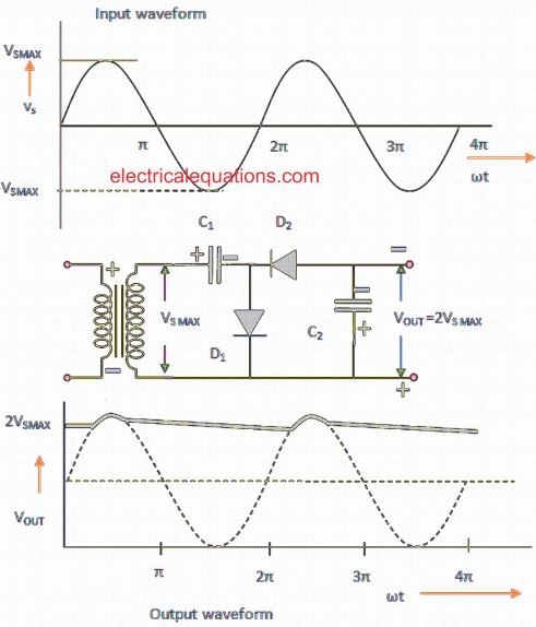
The figure below shows the input waveform, circuit diagram and output waveform. In this diagram , during the positive half cycle, the forward biased D1 diode conducts and diode D2 remains in switched OFF state.
At this point, the capacitor (C1) charges upto VSmax (peak 2° voltage). In the course of the negative half cycle, the D2 forward biased diode operates and D1 diode goes into a cut off situation. In this condition C2 begins charging.
Applying Kirchoff's voltage law = VSmax - VC1 + VC2 = 0 (outer loop) VC2 = VSmax + VC1 = VSmax + VSmax (since VC1 = VSmax) = 2 VSmax ➝ Two times the maximum value of 2° transformer voltage
In the course of the subsequent positive half cycle, D2 becomes reversed biased (blocking mode). In this condition C2 capacitor becomes discharged via the load and so voltage across this capacitor drops.
However in the absence of a load each of the capacitors goes into a charged condition. Meaning C1 is charged to VSmax and C2 is charged to 2VSmax.
Through the entire negative half cycle C2 becomes charged just as before (2VSmax). Within the next half cycle, a half wave that is filtered through capacitor filter is acquired over the capacitor C2. Right here, ripple frequency is identical to the signal frequency.
The DC output voltage as high as 3kV could be extracted from this kind of circuit.
Full Wave Voltage Doubler
The input waveform of full-wave voltage doubler can be seen in the following figure:
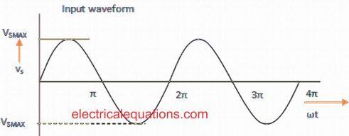
The diagram and output waveform is demonstrated in figure 3. Here during the positive cycle of input voltage, the diode D1 becomes forward biased and capacitor C1 becomes charged to VSmax(peak voltage).
During this period, D2 becomes reverse biased. During the negative cycle of input voltage, D2 becomes forward biased and capacitor C2 becomes charged. In the absence of a load the sum of the voltages of the two capacitors is received in the form of output voltage as:VC1 + VC2 = VSmax
If certain load is hooked up over the output terminals, in that case output voltage will be:(VL) < 2VSmax

We find that, both half-wave and full-wave voltage doubler deliver 2VS MAX as output without involving any transformer.
Here the diodes will need to be rated at peak inverse voltage equal to 2VS MAX. In comparison with half wave voltage doubler, the full-wave voltage doubler can easily separate out high frequency ripples and output ripple frequency adds up to two times the supply frequency.
However the difficulty in full-wave voltage doubler is the fact that; in between the input and output we have to include a common ground line.
Voltage Tripler and Quadrupler
Using the technique enhanced half-wave voltage doubler circuit, any voltage multipliers (Tripler, Quadrupler etc) could be developed.
Whenever the two capacitor leakage property and load are small-scale, a good deal of high DC voltages can be achieved through such circuits that consist of a number of stages to step-up (boost) the DC voltage.

At this point during the first positive and negative half cycles are similar to half-wave voltage doubler.
During the entire next positive half cycle, D1 and D3 operate and charges C3 to 2VSmax. All through the subsequent negative half cycle, D2 and D4 operate charging up C4 to 2VSmax.
If the number of diodes and capacitors are increased, every single capacitor is charged to 2VSmax.
Multiples of odd number at the output with values VSmax may be achieved, in case tested using the transformer 2° winding, and "even" multiples of VSmax could be accomplished, when assessed from bottom of 2° winding of transformer.
Application of Voltage Multiplier
- Ion pumps
- Copy machines
- Electrostatic systems
- Photomultiplier tubes
- Travelling wave tubes (TWT)
- Cathode ray tubes.
- Cathode ray tubes in oscilloscope, Television receivers, Computer display.
- X-Ray systems
- Lasers
- And several other devices which involves low current and high voltage applications.
can you please tell me in a first half cycle c1 is charging and due to diode d1 is in forward it’s short-circuit but why it’s not happen in the next half positive half cycle
When the AC voltage from the transformer is positive, then first diode D1 lets current flow and a capacitor gets charged up to the peak voltage. When the AC voltage swings negative, D1 becomes reversed biased then second diode D2 turns on and adds this charged-up voltage to the new input, passing both to the second capacitor. This second capacitor charges up to two times the peak value and that doubled voltage becomes the circuit’s output.