• Skip to main content
  • Skip to primary sidebar

Making Easy Circuits

Learn and build electronic circuits

You are here: Home / Voltage Regulators / Voltage Stepper Circuit or Voltage Booster Circuit

Voltage Stepper Circuit or Voltage Booster Circuit

Last Updated on January 10, 2018 by Admin Leave a Comment

The article details about a simple voltage stepper circuit also called voltage booster circuit which can be used in cases where the circuit is required to run on a rather higher voltage level than the existing supply.

The purpose of this project is to build a simple voltage stepper, which can be applied on the circuit when the power remain low. On a standard voltage multiplier circuit, the capacitors gets charged via diodes by AC power on one cycle and further discharges in another cycle. This process enable producing peak voltage. But here in this case we are not going to follow this policy. Instead we will adopt a different approach by doubling the DC instead of AC.

The following circuit diagram in Figure 1.0 illustrates the principle to build the voltage stepper:


voltage stepper circuit

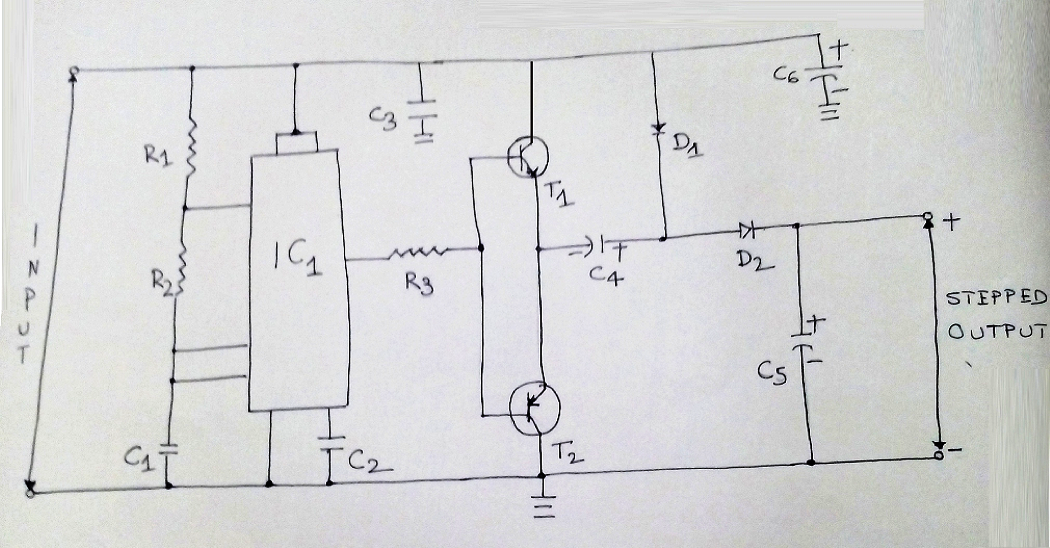
Referring to the figure, the IC555 is deployed to work as an astable multivibrator, which will generate rectangular pulse on the frequency of around 10kHz. The output of the IC555 is used to gear the transistor T1 and T2. As the type of T2 is PNP, ensure to conduct when the base remain negative, in other words, when the IC's output is low. This will further charge capacitor C4 through D1 diode and T2 is grounded.

On another situation when the output of the IC is in high state, T2 closes while T1 runs. Also during this state, C4 fail to discharge for the diode D1. In this way voltage in C4 and input voltage gets added and enable charge of C5 capacitor via diode D2. Furthermore, the available voltage in capacitor C5 equals to the pulse voltage of VCC over C4 and D1.

Aforesaid is the actual process of the operation. However, to build the system there is few consideration shared for understanding. On a situation when the current is more than 50mA, the regulation gets lost. But on DC voltage, if the current range between 5V – 18V, boosting is possible. Also to derive proper result it is ideal to increase value of C4 and C5 capacitors to 47 µF/40V.

Following are the parts that you need to build the voltage stepper circuit:

Resistors
R1240 Ω
R25.1 KΩ
R356Ω
Capacitors
C1, C2 103 ceramic
C3104 ceramic
C4, C533 µF/40v electrolytic
Semiconductors
IC1NE555 or any similar
T12N2222
T22N2907
D1, D2IN4007


You'll also like:

  • 1.  2 in 1 Light Dimmer Circuit with Touch Pad Operation
  • 2.  Car Voltage Stabilizer Circuit
  • 3.  AC Mains Current Detector Circuit
  • 4.  Simple Mains Overload Protection Circuit
  • 5.  High Current LM317 Variable Power Supply Circuit
  • 6.  120V 220V Over Voltage and Under Voltage Cut OFF Circuit Explained

About Admin

Hey friends, Thanks a bunch for stopping by this site! I am an engineer with a Bachelor of Engineering in Electronics and Telecommunication. One of my passions is gathering information from all sorts of electronics books and tutorials. I then take that information and compile it into a language that is super easy to understand. My goal is to make those complex electronics circuit concepts and technical terms much more accessible for all the new and budding electronics engineers out there. I can also design customized circuit diagrams as required by the users.
If you have any questions related to this field, please do not hesitate to drop a comment! I am always here and ready to help you out with any queries you might have. I cannot wait to hear from you!

Reader Interactions

Leave a Reply Cancel reply

Your email address will not be published. Required fields are marked *

Primary Sidebar

Categories

  • 3 Phase (4)
  • 8051 Microcontroller (1)
  • Arduino (11)
  • Audio and Amplifier (102)
  • Automation (8)
  • Battery Chargers (64)
  • Bicycle Projects (4)
  • Car and Motorcycle Projects (39)
  • Datasheets (10)
  • DIY Projects (5)
  • Electrical (15)
  • Free Energy (6)
  • Games Projects (2)
  • High Voltage (14)
  • Hobby Projects (30)
  • Household Circuits (2)
  • IC 555 Circuits (5)
  • Ignition Circuits (2)
  • Indicators (50)
  • Infrared (6)
  • Inverter Circuits (29)
  • Lights and Lamps (97)
  • Medical (8)
  • Meter and Tester Circuits (38)
  • Motor Driver (17)
  • New Circuits (56)
  • Oscillators (30)
  • Pets and Pests (5)
  • Power supply (80)
  • Protection Circuits (25)
  • PWM (9)
  • Remote Control (20)
  • Security and Alarm Circuit (48)
  • Sensors and Detectors (66)
  • Signal Processor (23)
  • Solar Controller Circuits (62)
  • SSR (3)
  • Temperature Controller (20)
  • Timer (25)
  • Transformerless (7)
  • Transmitters (12)
  • Tutorials (45)
  • UPS (2)
  • Voltage Regulators (57)
  • Water Sensor and Controller (29)
  • Home
  • Privacy Policy
  • Contact
  • Disclaimer
  • Copyright

© 2025 · Making Easy Circuits