• Skip to main content
  • Skip to primary sidebar

Making Easy Circuits

Learn and build electronic circuits

You are here: Home / Voltage Regulators / Zero Crossing 220V AC Light Dimmer Circuit using IC 555

Zero Crossing 220V AC Light Dimmer Circuit using IC 555

Last Updated on November 13, 2020 by Admin 7 Comments

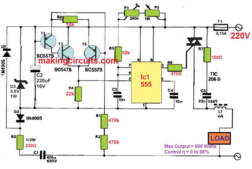
The post explains a high efficiency and versatile IC 555 based light dimmer circuit which works by phase control through zero crossing, thus eliminating noise and other issues associated with conventional light dimmers at 220V

The conventional dimmers employ a silicon-controlled rectifier like a triac or thyristor which is activated at preset phase angle and conducts until the next zero crossings of the mains voltage.

Although this method is simple, regulating small or inductive loads becomes a problem.

With the circuit in the discussion, the above problem is alleviated by introducing the triac with constant gate current so that power as low as 1 watt can be regulated.

To ensure the zero crossing light dimmer circuit is small, simple and compact, a 555-timer chip is utilized.

light dimmer zero crossing compressed
AC waveform compressed

How the Circuit Works

The standard active high of the 555 output is converted to active low using a negative supply voltage. This inverted power supply consists of a C1-R3 network, rectifiers D1 and D2, and a stabilizer D3-C2.

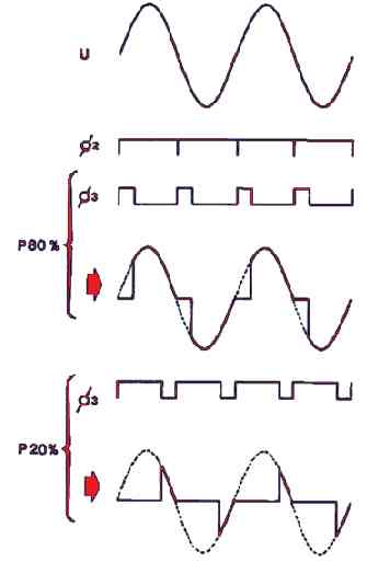
An initiation pulse is contributed by transistors T1 to T3 at the trigger input of the 555-timer chip during the zero crossing positions of the mains voltage. For an interval dictated by the setting of P1 and P2, the output of the timer is high.

Consequently, there is no voltage difference between pins 3 and 8 or in other words, the triac is switched off. Once the set interval has lapsed, pin 3 drops to low and as a consequent, the triac is activated.

A gate current flows for the remainder of the half period and ensures the triac is conducting. The minimum position (can be checked with a light bulb just before lighting) can be set with P1.

For the essential decoupling of the triac, filter in network R7-C5-L1 takes care of it. We also remind you to be observant as the maximum power that can be controlled using IC 555 zero crossing light dimmer circuit is 600 watts.

You'll also like:

  • 1.  High Current IC 555 Voltage Doubler Circuit
  • 2.  Simple Boost Converter Circuit
  • 3.  How to Build a Temperature to Voltage Converter Circuit
  • 4.  220V Touch Dimmer Switch Circuit with 4 Step Control
  • 5.  High Power Triac Dimmer Circuit for 1000 watt Loads
  • 6.  How to Build a 3 Phase VFD Circuit

About Admin

Hey friends, Thanks a bunch for stopping by this site! I am an engineer with a Bachelor of Engineering in Electronics and Telecommunication. One of my passions is gathering information from all sorts of electronics books and tutorials. I then take that information and compile it into a language that is super easy to understand. My goal is to make those complex electronics circuit concepts and technical terms much more accessible for all the new and budding electronics engineers out there. I can also design customized circuit diagrams as required by the users.
If you have any questions related to this field, please do not hesitate to drop a comment! I am always here and ready to help you out with any queries you might have. I cannot wait to hear from you!

Reader Interactions

Comments

  1. Jahangir says

    March 29, 2024 at 1:32 pm

    hi
    i made this circuit, but not respond, please help me, what i do

    Reply
    • admin says

      April 3, 2024 at 10:16 pm

      Hi, I cannot troubleshoot your circuit because I cannot check it practically…

      Reply
  2. Eric says

    August 17, 2023 at 11:56 pm

    Hi all, Very nice website and interesting circuits. About the zero crossing 220V ac dimmer circuit withe ic 555 I have a question. It not clear to me. R8 10k is this resistor connected to the fase line or to the collector of T3 (or to both). Thanks for reply,

    Reply
  3. Eric says

    August 17, 2023 at 11:51 pm

    Is the resistor R8 connected to the phase line or to the emitter of T3 (or both)?

    Reply
    • admin says

      August 20, 2023 at 11:28 am

      It is connected to both….

      Reply
  4. Omid Neichi says

    February 6, 2023 at 3:12 pm

    Hi there;
    I have been looking for this circuit. Although I previously got my hand on two old and assembled MEHRANKIT 3-chanel and 4-chanel rainbow kits which use similar circuits. Here one can read the theory and learn a lot. Anyway I hope it works accordingly
    Thanks,
    Omid Neichi

    Reply
    • admin says

      February 10, 2023 at 6:39 pm

      Hi, I hope the circuit works for you….all the best to you!

      Reply

Leave a Reply Cancel reply

Your email address will not be published. Required fields are marked *

Primary Sidebar

Categories

  • 3 Phase (4)
  • 8051 Microcontroller (1)
  • Arduino (11)
  • Audio and Amplifier (102)
  • Automation (8)
  • Battery Chargers (64)
  • Bicycle Projects (4)
  • Car and Motorcycle Projects (39)
  • Datasheets (10)
  • DIY Projects (5)
  • Electrical (15)
  • Free Energy (6)
  • Games Projects (2)
  • High Voltage (14)
  • Hobby Projects (30)
  • Household Circuits (2)
  • IC 555 Circuits (4)
  • Ignition Circuits (2)
  • Indicators (50)
  • Infrared (6)
  • Inverter Circuits (29)
  • Lights and Lamps (97)
  • Medical (8)
  • Meter and Tester Circuits (38)
  • Motor Driver (17)
  • New Circuits (56)
  • Oscillators (30)
  • Pets and Pests (5)
  • Power supply (81)
  • Protection Circuits (25)
  • PWM (8)
  • Remote Control (20)
  • Security and Alarm Circuit (48)
  • Sensors and Detectors (66)
  • Signal Processor (23)
  • Solar Controller Circuits (61)
  • SSR (3)
  • Temperature Controller (20)
  • Timer (25)
  • Transformerless (7)
  • Transmitters (12)
  • Tutorials (45)
  • UPS (2)
  • Voltage Regulators (57)
  • Water Sensor and Controller (29)
  • Home
  • Privacy Policy
  • Contact
  • Disclaimer
  • Copyright

© 2025 · Making Easy Circuits