A voltage stabilizer is a device which can be used to detect unsuitable voltage levels and rectify them to deliver a fairly steady output at the output where the load is connected.
Right here we are going to examine the design of an easy automatic mains AC voltage stabilizer which might be utilized for the above function.
How the Circuit Works
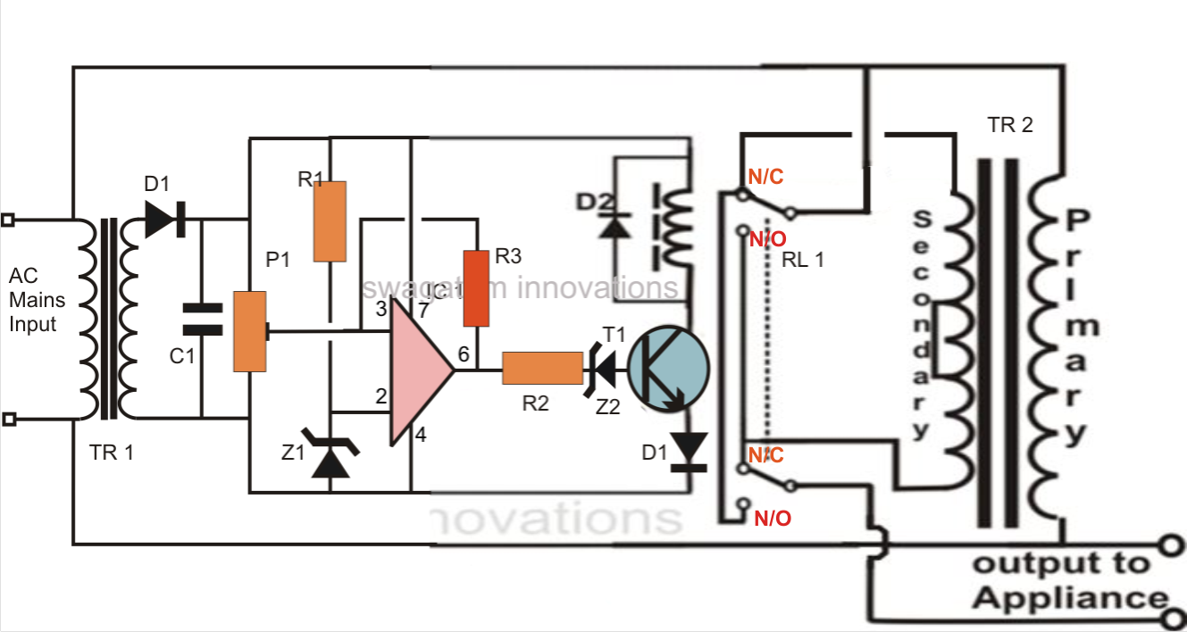
Talking about the figure we come across that the entire circuit is set up with the single op amp IC 741. It becomes the control section of the whole design.
The IC is wired as a comparator, everyone knows how well this mode suits the IC 741 and other op amps. It's two inputs are appropriately rigged for the stated procedures.
Pin #2 of the IC is clamped to a reference level, produced by the resistor R1 and the zener diode, while pin #3 is utilized with the sample voltage from the transformer or the supply source. This voltage evolves into the sensing voltage for the IC and is instantly proportional to the varying AC input of our mains supply.
The preset is employed to set the activating point or the threshold point at which the voltage might be believed to be harmful or improper. We are going to talk about this in the establishing process section.
The pin #6 which is the output of the IC, goes high the moment pin #3 gets to the set point and triggers the transistor/relay phase.
In the event the the mains voltage exceeds a specific threshold, the ICs non inverting identifies it and its output instantly goes high, activating the transistor and the relay for the required activities.
The relay, which is a DPDT type of relay, has its contacts wired up to a transformer, which can be a normal transformer improved to carry out the function of a stabilizer transformer.
It’s primary and secondary windings are correlated in such a manner that by means of suitable switching of its taps, the transformer has the capacity to add or deduct a particular magnitude of AC mains voltage and generate the subsequent to the output linked load.
The relay contacts are correctly incorporated to the transformer taps for performing the above actions as per the commands given by the op amp output.
So if the input AC voltage has a tendency to boost a set threshold value, the transformer deducts some voltage and tries to quit the voltage from achieving harmful levels and vice versa during low voltage circumstances.
220V voltage stabilizer circuit diagram
Parts List for the SIMPLE AUTOMATIC VOLTAGE STABILIZER CIRCUIT DIAGRAM
- You will require the following components to make this homemade automatic mains voltage stabilizer circuit:
- R1, R2 = 10K,
- R3 = 470K,
- P1 = 10K preset
- C1 = 1000 uF / 25 V
- D1, D2 = 1N4007,
- T1 = BC547,
- TR1 = 0 - 12 V, 500 mA,
- TR2 = 9 - 0 - 9 V, 5 Amp,
- IC1 = 741,
- Z1, Z2 = 4.7V/400mW
- Relay = DPDT, 12 V, 200 or more Ohms,
Approximate Voltage Outputs for the Given Inputs
INPUT------OUTPUT
200V -------- 212V
210V -------- 222V
220V -------- 232V
225V -------- 237V
230V -------- 218V
240V -------- 228V
250V -------- 238V
How to Set Up the Circuit
The suggested easy automatic voltage stabilizer circuit might be set up with the following procedures:
In the beginning do not hook up the transformers to the circuit.
Making use of a adjustable power supply, power the circuit across C1, the positive goes to the terminal of R1 while the negative goes to the line of D2’s cathode.
Set the voltage to about 12.5 voltage and adjust the preset so that the output of the IC just becomes high and causes the relay.
Now decreasing the voltage to about 12 volts should make the op amp trip the relay to its original state or make it de-energized.
Repeat and verify the relay action by modifying the voltage from 12 to 13 volts, which could produce the relay flip flop respectively.
Your starting process has ended.
Now you might hook up both the transformer to its suitable positions with the circuit.
Your simple home made mains voltage stabilizer circuit is ready.
When set up, the relay trips at any time the input voltage exceeds 230 volts, bringing the output to 218 volts and keeps this distance constantly as the voltage extends to higher levels.
When the voltage falls back to 225, the relay gets de-energized pulling the voltage to 238 volts and keeps the impact as the voltage further goes down.
The above activity keeps the output to the appliance well between 200 to 250 volts with fluctuations starting from 180 to 265 volts.
Daniel Figueiredo says
We will make public our discussions. No issue on that. The reason I am asking you for a verbal talk, because we can understand better that way. Writing does somehow not solve the problems at least with me. So, kindly make some time available for me and we will discuss in detail. Kindly oblige.I will tell you where I am right and so on etc, Remember I have sent you the circuits which I feel are right. Kindly let the discussion be somewhere in the night if it is possible with you.Thanks a lot.
Daniel Figueiredo says
I have repeatedly sent the circuits to you on the wordpress email but it has not reached you. Now I will upload them on [email protected]. No issue.
Admin says
I saw your diagrams, but I think those modifications are unnecessary and also incorrect.
The diagram shown in the above article has no issues, and should work good.
In your diagrams you have removed the zener diode from the base of the transistor which connects with the opamp output which is wrong. I can also see you have added another inverting transistor which is not required, also the transformer winding modifications are not required. In one diagram you have removed the opamp hysteresis resistor which is again wrong.
Daniel Figueiredo says
Can we talk at a convenient time to you. I do not say I am fully correct. But I will let you know why I made those corrections. My Mobile no.is +91 9881186594. I would be highly obliged if you could give me a chance to talk with You. I would be highly obliged. Thanks.
Admin says
I completely understand that talking live on phone would solve the issue quickly, however, i want the discussions to be also visible to the other users, so I would request you to discuss it here, on this platform.
By the way, the above circuit diagram is simple and will work correctly as intended, so we don’t want to complicate it further.
If you have any doubts regarding any of the components in the above diagram, please let me know, I will try to clarify it…
Daniel Figueiredo says
I have gone through your explanation Now I Have come to the conclusion that it depends how you add or substract the voltage at TR2. Now you say when the input to TR1 is 220 volts the relay is not energised I agree with that. The voltage at TR2 primary is220 volts the voltage at the secondary of TR2 is 12,5volts. As per the circuit diagram the voltage at he secondary of TR2 should be substracted from 220 volts as the voltage normally increases from the bottom to the top of the secondary winding of TR2 which is the normal convention.ie.It is positive 12.5 volts at the top and 0 volts at the bottom of secondary winding of TR2.Hence the voltage should be substracted as per the diagram. If it is opposite then the diagram is correct.In normal circumstances you should put a dot on top of the primary and secondary as I have indicated in my circuit diagram sent to you and adjust the circuit accordingly.as mentioned in my description and circuit diagram sent to you.
Next I feel there is no requirement of the components Z2 and D1. There is absolutely no need of these extra components. The circuit will work without these extra components. I hope you have received my circuits uploaded by me. Thanks.
Admin says
When same side wires of primary and secondary are joined then it adds up voltage, if opposite end wires are joined then it subtracts.
You can remove the emitter diode, but the base zener is crucial to avoid the leakage offset voltage from opamp output. If you don’t want the base zener then make sure to add a calculated pull-down resistor from base to ground.
The wordpress email does not work…
You can send the image to the following email:
hitman2008
@live.in
Vani says
hi, i want to use this ckt as voltge stabilizer for Tv and Fridge, is it possible if so what should be the turns of primary winding and secondary winding.
simultaneously will the values of the components value also will change.
im thinking of the high cut off should be at 280v.
Can you guide me .
Admin says
Hi, yes you can use it for the mentioned application.
280 is too high.
I would recommend no higher than 250V.
Daniel Figueiredo says
I have sent the corrected circuits by the following email-id
wordpress@makingcircuits,com which is yours.But the mail got bounced.Kindly send me your fresh email-id and I will send the circuits to you
Admin says
Hi, I tried your links again. The main link opens but the images never load….the download button does not work, none of the other direct links work. I checked it in all the browsers and the results were the same.
By the way I checked the diagram diagram in the above article, and I could not see anything wrong in it.
Here’s how it works.
Let’s say, initially the normal AC supply is 220V.
At this point the opamp output is not high, it is low so the relay is off at N/C points.
So the output adds up 12.5V to the 220V and it becomes 232.5V.
Now let’s assume the input AC voltage keeps rising until 230V, so the output becomes 230 + 12.5 = 242.5V, still manageable.
But at this point the opamp clicks ON and triggers the relay from N/C to N/O and the transformer deducts 12.5V from the supply making it 230 – 12.5 = 217.5V.
I hope you have now understood how the circuit works…
Johnny Michael Conales says
Is this applicable also using Step-down 220v to 45V Toroidal Transformer for the TR2. and does it stabilize the 45Vac output?
Admin says
Yes, it can be used…45V AC can be also stabilized proportionately…
Daniel Figueiredo says
Corrected 2 Automatic voltage stabilizer circuits have been sent to you today via email.
Daniel A.Figueiredo says
i saw the stabilizer circuit. I am just a bit confused, Initially suppose the relay is in normally closed condition. How does the voltage add up to the primary at the output? Kindly solve my difficulty.Thanks.
I think the automatic voltage stabilizer ckt. is wrong.If input voltage is more than the reference then the relay is going to switch.and then the voltage at the appliance will be high , higher than the boosted value at the reference at he input defeating the very reason the ckt.of the stabilizer is built
Admin says
Hey, the voltage adds up by doing the following transformer configuration:
https://makingcircuits.com/wp-content/uploads/2024/11/562fe4ba634b1786728190f82b2dafcfad4a7585_orig.jpg
https://makingcircuits.com/blog/how-to-build-2-stage-mains-power/
Daniel A. Figueiredo says
I maintain the circuit given above is wrong.When the set voltage is high ie. when the set voltage is high and equal to 12.5 volts at C1 the output of the comparator IC is high. Hence as a result the relay will be energised and the contacts will be in the normally open (N/O) condition . Thus the primary voltage at TR2 will be added with the secondary voltage giving a very high boost voltage.Actually the opposite should happen .The voltage at he secondary should be substracted from the primary since high voltage appears at the input of the primary at TR1 and you get 12.5 volts across C1.The corrected circuits will be sent by email to you,Thanks
Admin says
Hi, thanks for your kind efforts to correct this circuit.
On which email did you send the image?
Can you please upload it to any free image hosting site and send the link to me here…I will check it out…
Random_Man says
The question is whether there are calculations for resistors and capacitors
admin says
Resistors and capacitors may have calculations but it is not required since the values are not too critical.
yogesh says
how much KVA this stabilizer is, and how to calculate it. can i use single transformer and use different winding in single transformer.
admin says
It will depend on the transformer rating
Rajan says
Hello Sir. Thanks for the very informative projects that you are creating. Please can you specify the value of P1.Im trying to build a ac voltage stabiliser for a printer. The voltage is specified to be 220V constant. The printer heads are being damaged by varying ac voltage fluctuations in our country South Africa,due to the loadshedding . I would appreciate this very much . Thank you.
admin says
Thank you Rajan,
You can 10K for the preset P1.