• Skip to main content
  • Skip to primary sidebar

Making Easy Circuits

Learn and build electronic circuits

You are here: Home / Sensors and Detectors / Make this Simple Digital Clock using LM8650 IC Circuit

Make this Simple Digital Clock using LM8650 IC Circuit

Last Updated on January 16, 2025 by Admin Leave a Comment

The majority of electrical amateurs would want to build the circuit for the digital time clock that is described here.

You may have heard of digital clocks that use clock integrated circuits (ICs), such the well-known LM8361, MM5387, and others, however these ICs may be difficult to construct or highly outdated nowadays.

Functioning of Circuits

In regards to features and specifications, the current design is both significantly simpler and on par with its predecessors.

Additionally, this digital clock circuit has the benefit of a Duplex LED display model, which helps to simplify the design by lowering the number of interconnections and interconnections between the IC1 (LM8560) and the LED display.

We'll now examine the operation of the suggested digital clock circuit:

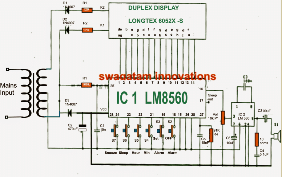
As can be seen from the above figure, the IC1 (LM8560), which is connected to the following output terminals, forms the circuit's heart:

  1. The output (pins 1–14) that drives the display's Duplex Model numbers
  2. Pin 16's output for producing an alert signal.
  3. The output choice, that may be used to use an integrated automated timer to operate external electrical equipment.

To enable a 50 Hz clock input to pin 25 of the IC, components R1 and C1 are included into the circuit.

In order to generate an alternating functioning of the display brightness in response to the input of IC1, the diodes D1 and D2 are positioned as rectifiers to act as signal generators to the cathode of the display number.

The amplifier stage for operating a loudspeaker when alarm triggers is formed by connecting the alarm signal via pin 16 of IC1 to a potentiometer P1 (Volume) and then integrating it with pin 3 of IC2 (LM386).

The purpose of the P1 is to give the alarm signal loudness an adjustment option. Furthermore, any additional required trigger circuit could possibly be controlled by the signal from pin 17's "sleep" pinout.

How to set the time in this digital clock

1. S6 is used to set hours.
2. S4 is used to set minutes.

The switches listed below can be employed for setting the alarm time:

1. S3 to hold down the time
2. S5 to set hours for the alarm.
3. S4 to set minutes for the alarmm.

The alarm might start to chime after the time range specified through S4/S5 has passed. This can be silenced by hitting switch S2, or really any other switch among those provided.

The switches listed below can be employed for controlling an outside equipment using clock triggers.

Switch S6 must be kept pushed at first.

For setting minutes, hit S4.

To adjust the hours, push switch S5.

    Pin 17 of the IC may be used to obtain the output signal for the ON/OFF control of equipment described above.

    For every repetition of an alert, use a time dilation alarm.

    You might wish to push switch S7 to activate this feature if you would like to repeat the alarm or prolong it for an additional nine minutes.

    Circuit Diagram

    Simple Digital Clock using LM8650 IC Circuit
    The Vdd pin is supposed to be pin #20, however it is incorrectly illustrated as pin #28. It is required that readers fix this error.

    You'll also like:

    • 1.  How to Make a Heart Rate Sensor with Processor Circuit
    • 2.  Metal Detector Circuit using a Single IC
    • 3.  How to Build a Insect Wing Signal Detector Circuit
    • 4.  Stress Level Detector Circuit
    • 5.  How to Build a Tuned Infrared (IR) Detector Circuit
    • 6.  Wire Current Detector Circuit

    About Admin

    Hey friends, Thanks a bunch for stopping by this site! I am an engineer with a Bachelor of Engineering in Electronics and Telecommunication. One of my passions is gathering information from all sorts of electronics books and tutorials. I then take that information and compile it into a language that is super easy to understand. My goal is to make those complex electronics circuit concepts and technical terms much more accessible for all the new and budding electronics engineers out there. I can also design customized circuit diagrams as required by the users.
    If you have any questions related to this field, please do not hesitate to drop a comment! I am always here and ready to help you out with any queries you might have. I cannot wait to hear from you!

    Reader Interactions

    Leave a Reply Cancel reply

    Your email address will not be published. Required fields are marked *

    Primary Sidebar

    Categories

    • 3 Phase (4)
    • 8051 Microcontroller (1)
    • Arduino (11)
    • Audio and Amplifier (102)
    • Automation (8)
    • Battery Chargers (64)
    • Bicycle Projects (4)
    • Car and Motorcycle Projects (39)
    • Datasheets (10)
    • DIY Projects (5)
    • Electrical (15)
    • Free Energy (6)
    • Games Projects (2)
    • High Voltage (14)
    • Hobby Projects (30)
    • Household Circuits (2)
    • IC 555 Circuits (5)
    • Ignition Circuits (2)
    • Indicators (50)
    • Infrared (6)
    • Inverter Circuits (29)
    • Lights and Lamps (97)
    • Medical (8)
    • Meter and Tester Circuits (38)
    • Motor Driver (17)
    • New Circuits (56)
    • Oscillators (30)
    • Pets and Pests (5)
    • Power supply (80)
    • Protection Circuits (25)
    • PWM (9)
    • Remote Control (20)
    • Security and Alarm Circuit (48)
    • Sensors and Detectors (66)
    • Signal Processor (23)
    • Solar Controller Circuits (62)
    • SSR (3)
    • Temperature Controller (20)
    • Timer (25)
    • Transformerless (7)
    • Transmitters (12)
    • Tutorials (45)
    • UPS (2)
    • Voltage Regulators (57)
    • Water Sensor and Controller (29)
    • Home
    • Privacy Policy
    • Contact
    • Disclaimer
    • Copyright

    © 2025 · Making Easy Circuits