SEVERAL audiophiles are finding some great benefits of graphic equalizers in domestic along with professional sound systems.
However the expenses of this sort of units have eliminated them growing to be as well-known as warranted through the several positive aspects they provide.
The benefits of an equalizer aren't usually popular but are the following: Initially an equalizer permits the listener to correct deficiencies in the linearity of either his speaker system alone, or the combination of his speaker system and his living room.
We have talked often times during the past, the actual most effective speakers obtainable are unable to provide accurate reproduction in an limited room.
This can be a unfortunate reality not many rooms are suitable, and quite a few of us endure the consequences of resonances and dips, regrettably sure that this is one thing we will need to survive along with.
Although the octave equalizer will not likely totally conquer this sort of complications, it is easy to reduce a few non linearities of the combined speaker/room system.
In a concert hall it might be possible to work with the unit to put a notch at the frequency just where microphone feedback takes place, hence enabling higher power levels to be employed.
Finally, for the serious audiophile, an equalizer is an extremely useful tool in considering the deficiencies within a specific system. One adjusts the equalizer to deliver a uniform reaction, the settings of the potentiometer knobs then graphically display the areas in which the speaker etc is lacking.
There exists a snag, nevertheless, one will need to have an informed ear to be able to correctly equalize a system to a flat response. It is far from very useful equalizing to your own choice of peaky bass etc so that you can assess a speaker.
Ultimately, a graphic equalizer need to ,possess filter at 1/3 octave intervals, but aside from sound studios and wealthy pop groups, the cost and size of this sort of units are usually a lot of for most of us.
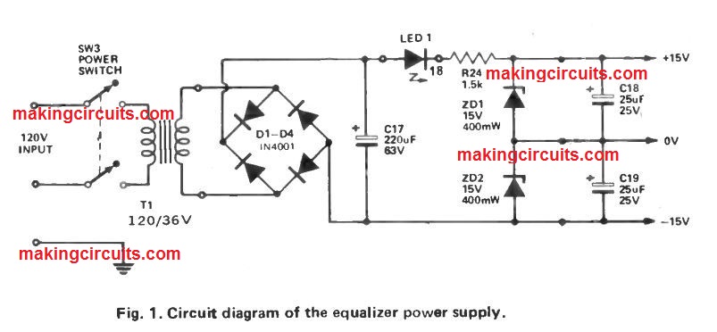
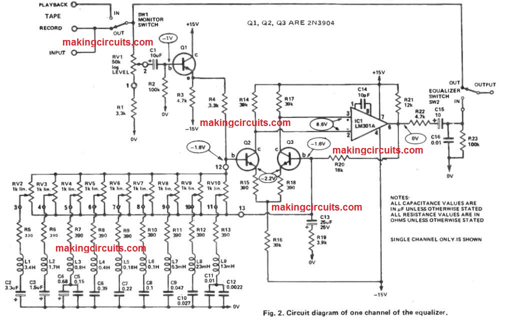
As a result of tolerances of resistors variations in Vbe of Q2 and Q3 etc, the constant state output of IC11 might be anywhere within plus or minus one volt of zero.
Therefore it is appealing to look for the polarity of the stable state voltage at pin 6 of IC1 so that you can figure out which way round C15 needs to be placed. In case the output is positive insert as displayed in Fig. 1. On the other hand C15 can be quite a non polarized sort.
How it Works
GRAPHIC EQUALIZER
The equalizer stage is a little strange in that the filter networks are usually organized to vary the negative feedback path across the amplifier.

If we think about one filter section only, with all others shut off, the impedance of the LCR network will probably be 390 ohms at the resonant frequency of the network.
At both side of resonance the impedance will certainly increase (using a slope based on the Q of the network which can be 2.5) as a result of uncancelled reactance.
This can be inductive above resonance and capacitive below resonance. We could hence signify the equalizer stage through the similar circuit as shown in Fig A below.
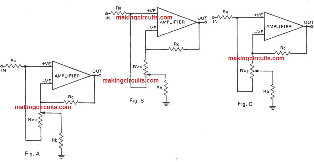
It should be emphasized that this similar circuit symbolizes the situation with one filter only, at its resonant frequency.
Furthermore letters are actually employed to specify resistors to prevent confusion with components in the actual circuit.
With the slider of the potentiometer at the top end (Fig. A) we now have 390 ohms to the OV line from the negative input of the amplifier, and 1 k amongst the two inputs of the amplifier.
The amplifier, as a result of feedback implemented, helps keep the potential amongst the two inputs at zero. Hence there is absolutely no current via RVA.
The voltage on the positive input to the amplifier is hence just like the input voltage because there is no current via, or voltage drop across resistor R a.
The output of the amplifier in this instance is around the input signal times (3300 + 390)/390 giving a gain of 19 dB. If the slider is at the other end of the potentiometer, as shown in the above Fig. B, the signal showing up at the positive input, thereby also the negative input, is around 0.11 (390/(3300 + 390) of the input.
There will probably still be no current in the potentiometer and in RC, thus the output will be 0.11 of the input. That may be, the gain will be -19 dB.
If the wiper is midway, both the input signal and the feedback signal are attenuated equally, and the stage will have unity gain.
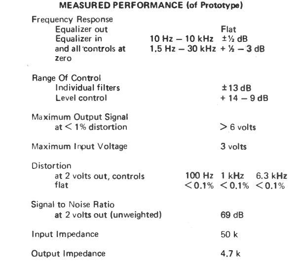
With all filter sections in circuit the maximum cut and boost accessible is decreased, but ±14 dB continues to be available. Reverting back now to the real circuit, the amplifier comprises of IC1, Q2 and Q3.
The transistors assist to decrease the impact of the noise in the IC and add gain at the high frequency end. This additional gain is needed because of the negative feedback, as a result of potentiometer amongst the two inputs, leads to high frequency roll off.
This does not influence operation of the unit presented the open loop gain is actually above 60 dB over the entire audio range. An overall closed loop gain of around 15 dB is managed by R20/R19 with the filter potentiometer at mid position.
The output of the amplifier is decoupled to the output of the unit through C15, and C16/R22 provide a cutoff above 30 kHz. The input signal is buffered by Q1 because the equalizer stage needs a low impedance signal source for right operation.
Potentiometer RV 1 delivers level control with 0 to 23 dB range which, along with the equalizer quality, leads to an entire level range of + 14 to -9 dB. The power supply utilized is an easy, full wave bridge filtered by C17.
Plus and minus supplies are produced by way of two 15 volt zeners in series fed through R24. The front panel power indicator is an LED linked in series using the dropping resistor R24.
Passive Graphic Equalizer
If you are one of those music enthusiast who take the variations and performance of the music quality very seriously, then this simple 5 band equalizer circuit can be one of your favorite music projects. This circuit has the ability to enhance any music into any desired bass and treble intensities.
Any electronic buff will understand that an audio related circuit is basically a design that is built for controlling the voltage peaks or amplitudes and frequency of a music signal such that the outcome gets tailored as per the users best listening pleasure.
The 5 band graphic equalizer circuit presented here is exactly meant for this utility, that is enhance an ordinary music signal into a desired high quality music output which may be either rich with low frequency bass, or high pitched treble response.
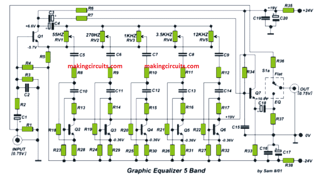
From the figure above, we can clearly see that the design is basically built by many transistorized tone controller stages, which are all individually adjustable.
The input signal is fed from the left side jack, which is not supposed to be less than 0.75V.
The various resistors capacitor based network at the input side are positioned to cut off high frequency noise or interference and allow genuine audio to proceed into the next stage.
The filtered low audio is fed to a differential BJT stage Q1 which amplifies this low to a audio into a reasonably high amplitude frequency.
This amplified differential response is delivered across an active 5 band BJT based tone processor stage, through their respective potentiometer terminals.
The potentiometer resistance along with the associated resistor capacitor networks form an adjustable inductance amplifier.
These components are uniquely configured for the 5 stages such that these modified inductors are able to control different levels of frequencies and allow only a specific band of frequency depending upon the pot adjustments.
For example the first stage controls the frequency range of 55Hz, which can be adjusted to pass high bass frequencies in the range of 10 to 55 Hz.
Similarly the subsequent 4 stages handle the frequency ranges of 270 Hz, 1KHz, 3.5 KHz and 12 KHz.
These 5 bands ensure that only the preferred bands of frequencies are equalized as per the precise needs of the listener.
The processed tone is finally delivered to another BJT stage Q7 which boosts the equalized music further in order to make it further enhanced and compatible with any power amplifier input.
The switch at the output of this 5 band equalizer circuit allows the user to select between a flat or direct music output or an equalized enhanced music output.
Parts list
- R1, R4, R37= 330k
- R2, R7= 2.2k
- R3= 120k
- R5, R6= 6.8k
- R8 to R12= 1.8k
- R13 to R15= 200k
- R16= 180k
- R17= 150k
- R18= 1.5k
- R19 to R22= 1k
- R23 to R27= 220k
- R28 to R32= 15k
- R33= 10k
- R34= 15M
- R35-38= 220Ω 1W
- R36= 100Ω
Capacitors
- C1 to C3 = 1uF 40V
- C2 = 68pF 100V
- C4 = 220uF 63V
- C5 = 1uF 100V
- C6 = 220nF 100V
- C7 = 47nF 100V
- C8 = 15nF 100V
- C9 = 5.6nF 100V
- C10 = 47nF 100V
- C11 = 15nF 100V
- C12 = 4.7nF 100V
- C13 = 1.5nF 100V
- C14 = 470pF 100V
- C15 = 68pF 100V
- C16-19 = 100nF 100V
- C17-20 = 470uF 40V
- C18 = 4.7uF 63V
- RV1....5= 50K Lin.
- Q1 tp Q7= BC550C
- S1= 2X2 SW
What is the components value of This 5 band circuit +??
I have updated the parts list!