Current in all 78XX ICs such as 7812, 7805, 7824 etc is internally restricted to 1 amp only. In this post we learn how to boost current from these ICs using an outboard transistor circuit with a 78XX circuit.
There are several options of pulling extra current from a 78XX type voltage regulator lC than it was original rating, however the majority of techniques have their down sides, In case, for example, a power transistor is attached in parallel with the IC, the supply voltage may not be safeguarded from short-circuits.
That may, naturally, be dealt with with the addition of a current sensor in the form of an additional transistor that, while in overload situations, cuts off the base current for the power transistor. Nevertheless this particular remedy can experience great power loss in the course of short-circuit situations, that is not truly suitable either.
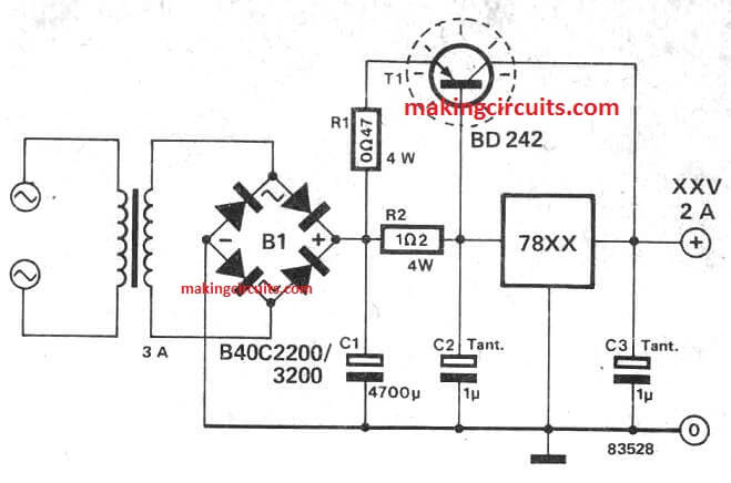
The current booster circuit for 7812, 7805 ICs offered in this article demonstrates that a less complicated solution might be achievable: the power transistor, T1, is presented with an emitter resistor!
This successfully handles the problem, due to the fact the current via T1 is then proportionate to the current delivered through the voltage regulator. In case the 78XX regulator and T1 are attached onto the same heatsink, the transistor is additionally thermally guarded!
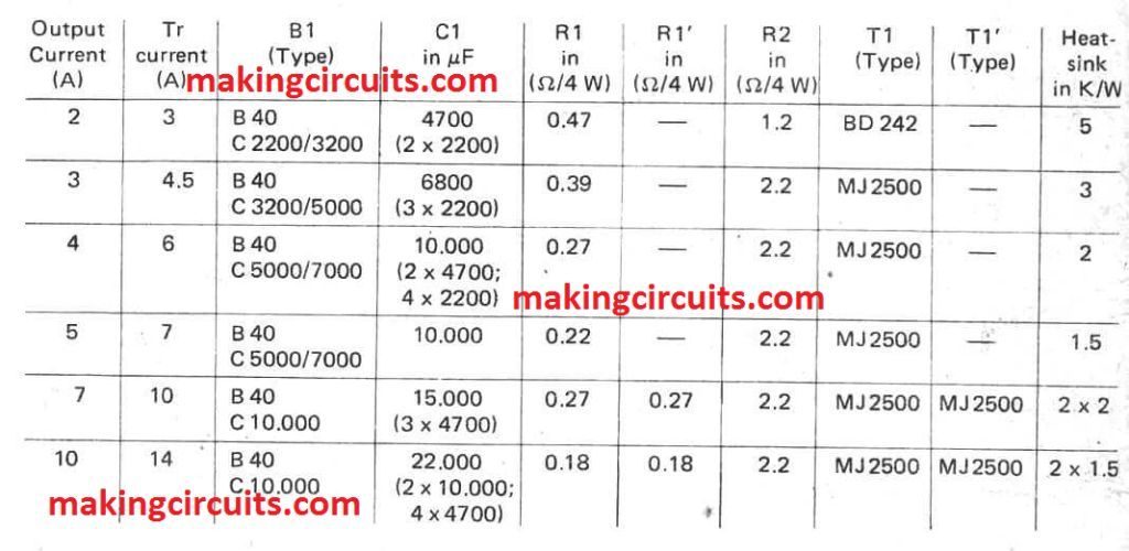
The output voltage will depend merely on the type of voltage regulator used and, as presented here, the circuit is well suited for currents as much as 2 A. If greater values are needed, a number of parts might have to be modified based on the given chart below.
To increase currents over 7 A, transistor T1 should be substituted by a couple of parallel attached transistors each of containing an emitter resistor, R1 and R1' respectively.
It is difficult to place both the 7812 and MJ2955 on the same heatsink because their metal bodies are connected to different polarities. The 7812 tab is internally connected to ground, while the MJ2955 metal case is connected to positive supply. Therefore an insulating mica sheet and insulating bush must be used, otherwise a short circuit will occur.
Yep, thanks for the valuable suggestions, much appreciated!!
Thank you for your idea!
You are welcome Sudy!!
The circuit is using outdated transistors and is quite more expensive than using a suitable voltage regulator that handles the current directly. Most modern regulators are a lot more effective than this one, have additional features like low dropout voltage, better ripple rejection, smaller capacitors requirements, and _real_ thermal protection. In this circuit, by putting both elements on the same heatsink, at the time the transistor heat has traveled all the way through the heatsink and triggers 78xx thermal protection, the transistor is long gone. Don’t use this. There are cheap alternatives: Question above, use a LM317 plus 3 resistors, voila: Battery charger (see LM317 datasheet). 2 resistors, 2 capacitors, 1 diode, 1 inductor, voila: 5 A current with XL5006.
You can use TIP32 or TIP36.
This design is highly customizable.
I would like to protect the battery from overcharging
12V will not charge a 12V battery….
for auto cut off you can add the following op amp stage at the output of the above 78XX design
https://makingcircuits.com/blog/automatic-12v-battery-charger-circuit/
hello I make the ic 7812 current booster circuit with 2 transistors to have a load of 7 amp, how I can put an automatic cut off on this circuit
Thank you
what kind of auto cut off are you asking for? please explain it in detail