Here we are talking about a simple way that we can make our submersible pump to start and stop automatically without we touching any button and also we can keep the dry run protection so that the motor never gets damaged.
This system will work in such a way that the motor will start or stop by itself depending on the high or low water levels of the overhead tank.
Circuit concept
We remember in one of our older discussions we saw one similar idea that also was doing the automatic start stop function for a submersible pump contactor button but in that old method the sensors were float switches, so the whole wiring and arrangement looked a bit complicated and not for everyone to easily make.
Also in that older method the dry run protection was done by depending on the temperature change of the motor and that was used to trigger the motor protection but for a normal person this was not nice because putting a heat sensor over an underground motor is not a simple thing at all.
So in this new explanation we remove all these difficulties and we design a circuit which can detect the water availability only through simple metal sensors which we put inside the correct water sources. This way we do not need any float switch or temperature sensor.
Circuit operation
Now we try to understand how this new automatic submersible pump start stop circuit with dry run protection will actually work.
Operation with ic 4049
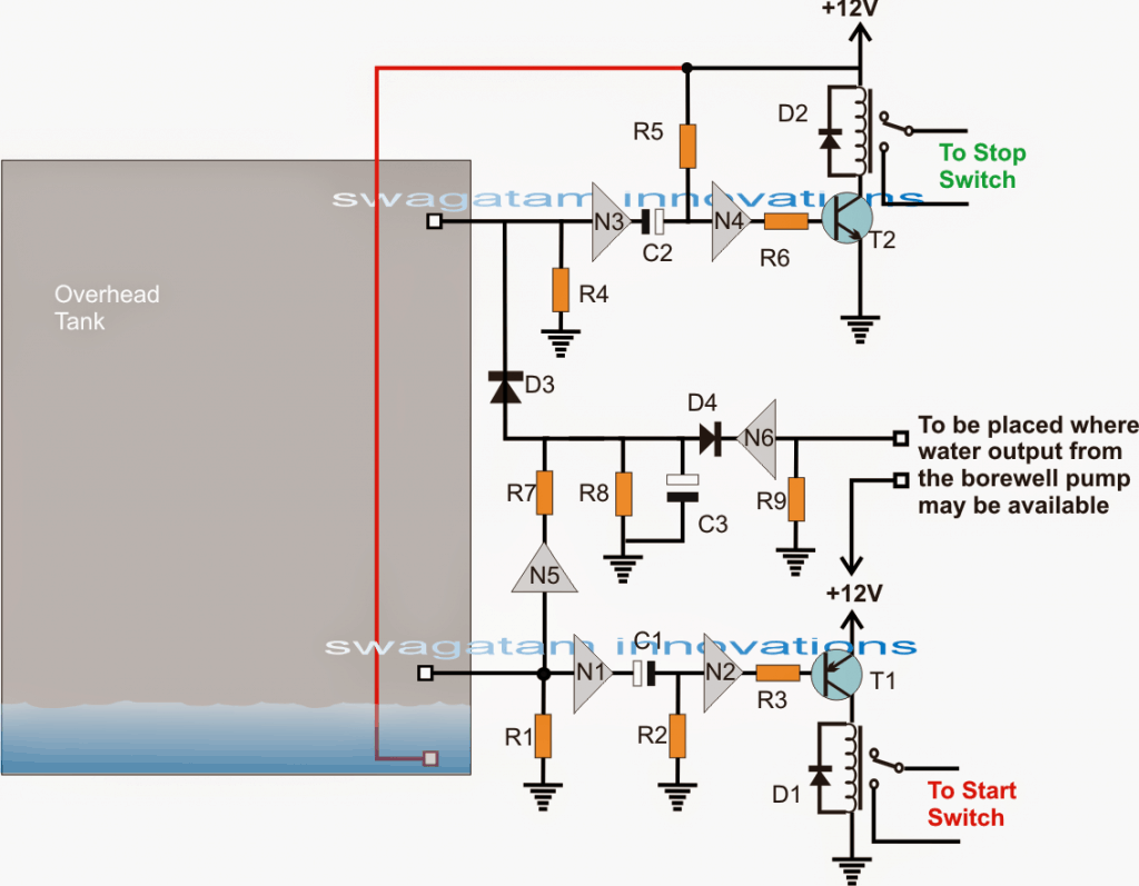
Here we are using only one ic 4049 for doing all the sensing work, the start stop action and also the dry run protection. Inside this ic we have total 6 not gates and we connect them as inverters so that they can change the polarity of the voltage that we give on their input pins.
Now let us say the water in the over head tank goes down below the lower threshold level shown in the diagram.
Then the positive voltage which was going through the water to the input of N1 stops reaching there. N1 then reacts and makes a positive voltage appear at its output pin. This positive then starts charging C1 through R2.
At the same time the positive from N1 output also goes to the input of N2. Then N2 output becomes low or negative and this low goes through R3 to the base of transistor T1.
This makes the connected relay turn ON and press the start button of the contactor. But the relay will remain ON only for a second or little more until C1 fully charges. We can change this ON time by changing the values of C1 and R2.
For now we ignore the N5 and N6 stage because they are for dry run protection.
Now we think the pump is running and it is sending water into the over head tank. The water keeps rising until it touches the top level sensor which is connected to the input of N3.
Then a positive voltage passes through the water to the N3 input. This makes the N3 output low or negative and at the same time C2 starts charging through R5.
Also the input of N4 becomes low so its output becomes high and this high makes the relay driver activate the relay.
This top level relay works only for a second and it presses the stop button of the contactor and the pump stops. The time for which the relay works can be set by changing the values of C2 and R5.
This is how the automatic water level control works for start stop of the submersible pump using the two relays. Now we see how the dry run protection works to save the pump when there is no water in the borewell or underground tank.
We go back to the first condition when the water in the over head tank was below the lower threshold and we had a low at the input of N1.
This also makes the input of N5 low. N5 then gives a high output and this high starts charging C3.
But at the same time we are starting the motor and if water is present then the pump will send water to the over head tank.
This water is detected by the input of N6 and this makes the N6 output low. When N6 output becomes low then C3 cannot charge further and the situation remains as it is and the motor keeps running normally.
But suppose there is no water in the well and the pump is running in dry condition. Then as said earlier C3 starts charging and since N6 never gets any signal from water its output never becomes low to stop C3 from charging.
So C3 goes on charging until the time decided by C3 and R8 is over. After this time C3 produces a high voltage at the input of N3.
N3 then works in the same way as when the water in the tank touches the top level sensor. It activates the upper relay for a second and this relay presses the stop button of the contactor and the motor stops.
This is how the dry run protection happens in this automatic submersible pump start stop circuit.
Parts List
| Part(s) | Value / Type | Notes |
|---|---|---|
| R1, R4, R9 | 6M8 | — |
| R3, R7, R6 | 10K | — |
| R8 | 100K | — |
| R2, R5, C1, C2, C3 | To be determined experimentally | Depends on timing requirement |
| N1 — N6 | IC 4049 | 6 NOT gates inside |
| All Diodes | 1N4007 | — |
| Relays | 12V, 10A | For contactor start/stop |
| T1 | BC557 | PNP transistor |
| T2 | BC547 | NPN transistor |
Leave a Reply