The construction of a basic bicycle speedometer circuit that may be utilized to measure a bike's speed will be the subject covered in this article.
How a Bicycle Speedometer Operates and What It Is
An instrument called a bicycle speedometer measures the speed of the wheel's revolution per minute and shows the findings on a meter to show how quickly the bike is moving.
A bicycle speedometer essentially operates as follows:
- One of the bicycle's tires has a sensor mounted on it.
- Typically, the sensor will be a magnet-based sensor, which could be a magnetic reed switch sensor or a magnetic hall effect sensor.
- The permanent magnet is fastened on the spoke itself, while the hall effect sensor or reed relay is mounted on the bicycle's wheel chassis.
- The magnet and sensor are fastened together to ensure that the magnet and sensor contact each other while the wheel revolves.
- In this manner, the magnet produces a momentary magnetic field on the sensor with every single wheel rotation, cutting across the sensor and producing a matching electrical pulse at the sensor's output.
- A central processing unit receives this electrical pulse, interprets the sensor output signals for each wheel revolution, and shows the outcome on a meter.
- Consequently, the meter shows the bicycle's speed.
Which idea is applied to our circuit?
Three basic approaches to building a bicycle speedometer circuit will be discussed in this article:
By Combining a Dynamo and a Meter
Combining LEDs and the LM3915 circuit
Mixing a magnet and a Hall effect sensor
1) Using a Voltmeter alone
Connecting a tiny digital or analog voltmeter to the present bicycle dynamo, as seen in the accompanying image, is the simplest method to determine the speed at which your bike is advancing:
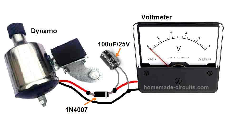
A 100uF filter capacitor and a 1N4007 rectifier diode are used to link a 0–5V voltmeter to the dynamo wires, as seen in the illustration above. To lessen the noise on the meter needle at low bike speeds, the above capacitor might be raised to 1000uF. The cathode or ringed edge of the 1N4007 is linked to the capacitor's positive lead, while the other wire of the dynamo is straight hooked up to the capacitor's negative lead.
The widest spectrum of the specified meter in this case is 5V, however according to the highest possible voltage production capability of your dynamo and the top speed of your bicycle, we could utilize a meter having an expanded range of up to 12V or 24V.
The circuit operates in a straightforward manner. The speed of your bicycle wheel determines how much electricity your dynamo produces.
In other words, the voltmeter detects that the dynamo shaft of electricity is rotating more quickly in response to your bicycle's growing speed, and it displays a correspondingly rising volt value on the meter.
The speed of the bicycle is shown by this voltage measurement, which is exactly related to your bike's speed.
Leave a Reply