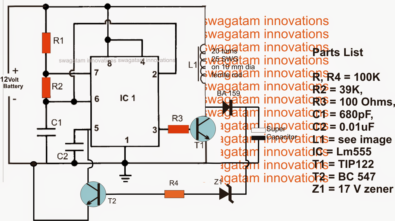
The submit describes a basic increase converter circuit which transforms a 12V car battery volatge to an elevated 16V for charging a bank of super capacitors.

The offered boost charger circuit for charging super capacitor banks might be observed in the above figure.
The total circuit can be viewed wired around the ubiquitous IC 555, set up as a high frequency astable.
High frequency is needed in an effort to generate a compact ferrite coil which turns into to blame for generating the needed stimulated voltage.
The fairly low current output from the IC is heightened utilizing T1 which switches the linked ferrite inductor at the rate of the given astable frequency.
The above steps encourages a determined boosted voltage across the coil which happens to be correctly improved making use of the connected BA159 quick recovery diode.
The subsequent voltage at the cathode of the diode is provided to the connected super capacitors for the meant charging of the devices.
A opinions loop may be seen from the output to the base of T2 which guarantees a completely maintained voltage for the super capacitors....in case the voltage is likely to rise above the specific fixed value, Z1 receives forward biased and switches ON T2 which often grounds pin5 of the IC choking the pulse width of the pin3 frequency.
This process immediately decreases the output to the safe limits and the cycle maintains switching making sure the voltage constantly remains within the arranged thresholds.
Hi, I think this circuit is what I need,I like to know what is the max and min capacity of supercap bank it can carry on a safe level in terms of capacitance and voltage. Thank you.
It will depend on the supply input, the power device and the coil rating….by upgrading these any desired magnitude can be reached