• Skip to main content
  • Skip to primary sidebar

Making Easy Circuits

Learn and build electronic circuits

You are here: Home / Car and Motorcycle Projects / Brake Lights Monitor Circuit

Brake Lights Monitor Circuit

Last Updated on April 6, 2020 by Admin Leave a Comment

This brake lights monitor circuit is used to monitor the brake lights of a car and tell if they are both working through an LED illumination. This ensures both road safety and prevention of fines due to faulty brake lights.

The design works by detecting the drop in the voltage supply to the lamps, which must be at least 0.6 V.

If that is not so, it should be amplified using 5 A diodes in series with each of the lamps.

How the Circuit Works

brake light monitor

A Schmitt trigger formed from T1 and T2 is used to create the response to the voltage drop, which is the lighting of D1 through T3.

LED D1 will light for a moment when pressing the brakes due to the switch-on current to one lamp if the other is defective. If both are not working, D1 will not light up at all. Thus, all possible scenarios are covered through the LED illumination.

P1 is used to control the hysteresis of the trigger and thus, the circuit sensitivity within narrow limits. It is best to set the preset condition with one lamp off and D1 lighting momentarily.

If you do not like a light, ie, D1, lighting up each time you press the brakes, you can replace the BC557 at T3 with a BC547B (n-p-n) to reverse the situation.

T3 is then fitted such that the emitter is connected to R6 and the collector to the positive supply.

This is done by turning the flat face of T3 the other way on the printed circuit board. There is also a second base connection provided on the PCB.

This form of the circuit has a disadvantage - the LED lights up regardless of whether one lamp stops working or both.

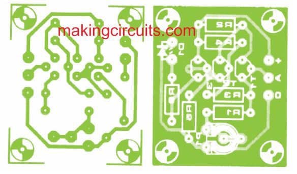
Note that you will not find the PCB in the market, it will need to be made to order using the following track layout.

brake light pcb

In the brake lights monitor circuit diagram, the brake pedal switch is denoted by S1 and the brake lights by La1 and La2.

You'll also like:

  • 1.  How to Make a Wireless Helmet Brake Light Circuit
  • 2.  How to Make a Car Battery Voltage Monitor Circuit
  • 3.  How to make a Car Interior Light Fader Circuit
  • 4.  Headlight Reminder Warning Circuit
  • 5.  How to Make a Cellphone RF Triggered Car Amplifier Auto-Mute Circuit
  • 6.  Variable Windscreen Wiper Delay Circuit

About Admin

Hey friends, Thanks a bunch for stopping by this site! I am an engineer with a Bachelor of Engineering in Electronics and Telecommunication. One of my passions is gathering information from all sorts of electronics books and tutorials. I then take that information and compile it into a language that is super easy to understand. My goal is to make those complex electronics circuit concepts and technical terms much more accessible for all the new and budding electronics engineers out there. I can also design customized circuit diagrams as required by the users.
If you have any questions related to this field, please do not hesitate to drop a comment! I am always here and ready to help you out with any queries you might have. I cannot wait to hear from you!

Reader Interactions

Leave a Reply Cancel reply

Your email address will not be published. Required fields are marked *

Primary Sidebar

Categories

  • 3 Phase (4)
  • 8051 Microcontroller (1)
  • Arduino (11)
  • Audio and Amplifier (102)
  • Automation (8)
  • Battery Chargers (64)
  • Bicycle Projects (4)
  • Car and Motorcycle Projects (39)
  • Datasheets (10)
  • DIY Projects (5)
  • Electrical (15)
  • Free Energy (6)
  • Games Projects (2)
  • High Voltage (14)
  • Hobby Projects (30)
  • Household Circuits (2)
  • IC 555 Circuits (5)
  • Ignition Circuits (2)
  • Indicators (50)
  • Infrared (6)
  • Inverter Circuits (29)
  • Lights and Lamps (97)
  • Medical (8)
  • Meter and Tester Circuits (38)
  • Motor Driver (17)
  • New Circuits (56)
  • Oscillators (30)
  • Pets and Pests (5)
  • Power supply (80)
  • Protection Circuits (25)
  • PWM (9)
  • Remote Control (20)
  • Security and Alarm Circuit (48)
  • Sensors and Detectors (66)
  • Signal Processor (23)
  • Solar Controller Circuits (62)
  • SSR (3)
  • Temperature Controller (20)
  • Timer (25)
  • Transformerless (7)
  • Transmitters (12)
  • Tutorials (45)
  • UPS (2)
  • Voltage Regulators (57)
  • Water Sensor and Controller (29)
  • Home
  • Privacy Policy
  • Contact
  • Disclaimer
  • Copyright

© 2025 · Making Easy Circuits