The following article presents a basic circuit for a charger for mobile phones with a timer that can be used to charge a particular mobile phone for a predefined amount of time. Mr. Sandars requested the concept.
Circuit Requirements and Objectives
Would you be able to create this charging circuit for me personally?230V 60 Hz input and three USB ports on the output for mobile charging.
A timer with three different time settings—30, 60, and 120 minutes—is all I need for this circuit.
I plug my phone into any of the three USB ports, hit the on/off button and after a certain amount of time—say, 60 minutes—the electricity goes out.
I hope you can comprehend what I'm asking for.
Circuit Diagram
Working of the Circuit
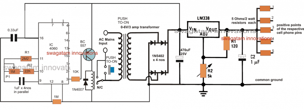
The above image shows the suggested cellphone charger circuit with timer. Its main components are a DC to DC multi-cell phone charger stage and an IC 4060 timer stage.
The mobile phone charger part uses a conventional charger circuit based on the LM338. Its output is divided into five separate charging outputs making it possible to charge five different smartphones. Three channels, each with a 1500mAH capacity may be used to charge the three mobile phones that were intended. Ohm's law may be used to determine the series resistors as indicated below.
R = V/I = 5/1.5 = 3.33 ohms, 10 watts each
In order to obtain about 5V across the output terminals or across C2, R2 in the LM338 circuit needs to be properly tuned.
The IC 4060, whose pinouts are likewise set up in its typical timer/counter mode, makes up the timer stage.
It is possible to modify P1 such that pin#3 has a delay duration of around 120 minutes. This would enable pin#2 to cause a 60-minute delay and pin#1 to provide a 30-minute delay.
At first, the timer-equipped smartphone charging circuit remains dormant and refuses to respond whenever power is provided across the designated mains input terminals.
But as soon as the designated push button is touched, the relay's N/O side connects to the other disconnected mains line.
By temporarily connecting the transformer leads to the AC mains, the rectifier stage is powered, allowing the IC 4060 timer stage to have a temporary DC supply input.
In addition to turning on the timer, this brief supply to the IC 4060 stage creates the starting zero potential at the base of the relay driver BC557 transistor, turning the relay on from N/C to N./O points.
Following this, the relay contacts assume control of the push-to-ON switch connections, enabling AC to pass through them and into the transformer primary.
This guarantees that the circuit may now latch into the powered state even if the push button is disengaged, allowing the LM338 to start charging the connected mobile phones and the timer IC 4060 to use the pot P1 to count down the allotted period of time.
When the IC 4060's counting is over, pin #3 (or pin #1 depending on which is used) goes high, turning the BC557 and the relay contacts back from N/O to N/C.
By immediately turning off and disconnecting the transformer's mains AC, this step deactivates the whole procedure and returns the whole thing to its initial alert state.
All it would take to restart this phone charger timer circuit is to click the push button for the next
Time Delay for the IC 4060 can be calculated using the formula:
- f(osc) = 1 / 2.3 x Rt x Ct
- where Rt = R2 +P1 (in Ohms)
- Ct = C1 (in Farads)
Parts List
| Component Type | Specification | Quantity |
|---|---|---|
| Resistors (1/4 watt, 5%) | 2M2 | 1 |
| 22K | 1 | |
| 10K | 1 | |
| 1M | 1 | |
| 120 ohms | 1 | |
| 1M Potentiometer | 1 | |
| 5K Potentiometer | 1 | |
| Capacitors | 1uF/50V Non-polar | 4 |
| 0.33uF | 1 | |
| 470uF/25V Electrolytic | 1 | |
| 1uF/25V Electrolytic | 1 | |
| Diodes | 1N4007 | 5 |
| Transistor | BC557 | 1 |
| IC | LM338 | 1 |
| Relay | 12V/400 ohms | 1 |
| Push Button | - | 1 |
| Transformer | 0-12V, 5 Amp | 1 |
| Output Resistors | As per the given formula |
Leave a Reply