• Skip to main content
  • Skip to primary sidebar

Making Easy Circuits

Learn and build electronic circuits

You are here: Home / Audio and Amplifier / Designing a MOSFET Power Amplifier Circuit

Designing a MOSFET Power Amplifier Circuit

Last Updated on June 6, 2025 by Admin 5 Comments

We know that a design using complimentary emitter follower transistor significantly increases the output power of an operational amplifier.

Similarly for achieving highly increased output power MOSFETs amplifier can be designed as complimentary source follower.

However, this would also result in the maximum output voltage getting reduced significantly by the gate source of the MOSFET by a couple of volts.

How the Circuit Works

Connecting two MOSFETs as a complementary drain follower could also be used. The level of the supply voltages and the saturation voltages of T3 and T4 limits the output current provided by the MOSFETs.

Resistor R8 and R9 are responsible for providing feedback for the opamp and the MOSFETs. There is an increase in the open-loop amplification of the opamp by (1+ R8/R9). (1+R3/R2) is the closed-loop amplification of the complete amplifier.

mosfet amplifier

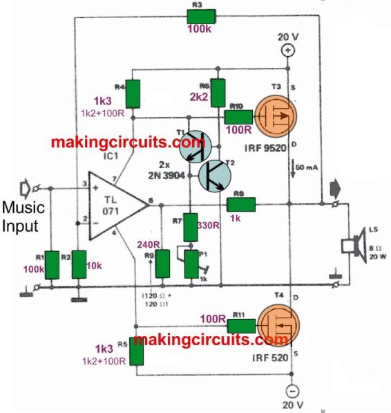
The arrangement of quiescent current of T3 and T4 at 50mA is completed but the current source formed by T1 and T2.

The direct current through the opamp resulting in the voltage drop across the resistors should not be sufficient to switch onT3 and T4, so the values of R4 and R5 should be regulated.

The rise in the voltages across R4 and R5 increases the quiescent current through T3 and T4, depending on the setting of P1 and depending on the current source.

T2 must be mounted on the common heat sink (c. 5 K/W) of the MOSFETs, in view of the temperature dependence of the quiescent current.

In this simple MOSFET amplifier design the harmonic distortion is equal to 0.075 percent at 100Hz and to 0.135 per cent at 10kHz when the output power is not less than 20W into 8 Ohm.

You'll also like:

  • 1.  Precision Guitar Tuner Circuit
  • 2.  VHF Preamp Circuit
  • 3.  Buzzer Circuit Using a Transistor and Piezo Element
  • 4.  Scratch And Rumble Filter Circuit
  • 5.  Simplest Homemade Electric Guitar
  • 6.  Electronic Bongo Circuit

Tagged With: Amplifier, Designing, MOSFET, Power

About Admin

Hey friends, Thanks a bunch for stopping by this site! I am an engineer with a Bachelor of Engineering in Electronics and Telecommunication. One of my passions is gathering information from all sorts of electronics books and tutorials. I then take that information and compile it into a language that is super easy to understand. My goal is to make those complex electronics circuit concepts and technical terms much more accessible for all the new and budding electronics engineers out there. I can also design customized circuit diagrams as required by the users.
If you have any questions related to this field, please do not hesitate to drop a comment! I am always here and ready to help you out with any queries you might have. I cannot wait to hear from you!

Reader Interactions

Comments

  1. Chandrashekar says

    May 2, 2023 at 11:12 am

    I have a 75 + 75 W MOSFET power amplifier, what is the minimum input voltage required, or if it is more than allowable please advice how to reduce on preamplifier out put.

    Reply
    • admin says

      May 9, 2023 at 11:56 am

      Minimum input voltage can be around 15 V. Preamplifier output can be controlled by adding a volume control pot between the preamp output and power Amp input.

      Reply
  2. Nico says

    May 2, 2021 at 5:46 pm

    Hi Admin,
    Thanks a lot!
    Have a nice day.
    Nico

    Reply
  3. Nico says

    April 19, 2021 at 12:20 am

    Hi, im considering to build this amp.
    How is the sound and is it possible to increase the quiescent current for example to 100-200mA?

    Thanks in advance!
    Nico

    Reply
    • admin says

      May 2, 2021 at 5:22 pm

      Hi, surely you can try this circuit….the quiescent current must be kept to the minimum otherwise there will be unnecessary drain of current, and MOSFET will heat up….but anyway you can adjust it by tweaking the P1 1k preset…sound will be of good quality

      Reply

Leave a Reply Cancel reply

Your email address will not be published. Required fields are marked *

Primary Sidebar

Categories

  • 3 Phase (4)
  • 8051 Microcontroller (1)
  • Arduino (11)
  • Audio and Amplifier (102)
  • Automation (8)
  • Battery Chargers (64)
  • Bicycle Projects (4)
  • Car and Motorcycle Projects (40)
  • Datasheets (10)
  • DIY Projects (5)
  • Electrical (15)
  • Free Energy (6)
  • Games Projects (2)
  • High Voltage (14)
  • Hobby Projects (30)
  • Household Circuits (2)
  • IC 555 Circuits (4)
  • Ignition Circuits (2)
  • Indicators (51)
  • Infrared (6)
  • Inverter Circuits (29)
  • Lights and Lamps (97)
  • Medical (8)
  • Meter and Tester Circuits (38)
  • Motor Driver (17)
  • New Circuits (56)
  • Oscillators (30)
  • Pets and Pests (5)
  • Power supply (82)
  • Protection Circuits (25)
  • PWM (8)
  • Remote Control (20)
  • Security and Alarm Circuit (48)
  • Sensors and Detectors (66)
  • Signal Processor (23)
  • Solar Controller Circuits (61)
  • SSR (3)
  • Temperature Controller (20)
  • Timer (25)
  • Transformerless (7)
  • Transmitters (12)
  • Tutorials (45)
  • UPS (2)
  • Voltage Regulators (57)
  • Water Sensor and Controller (29)
  • Home
  • Privacy Policy
  • Contact
  • Disclaimer
  • Copyright

© 2025 · Making Easy Circuits