• Skip to main content
  • Skip to primary sidebar

Making Easy Circuits

Learn and build electronic circuits

You are here: Home / Security and Alarm Circuit / Door Lock Circuit using Digital Code

Door Lock Circuit using Digital Code

Last Updated on January 10, 2018 by Admin Leave a Comment

In this post we try to analyze a simple door lock circuit using digital code that needs to pressed with a unique sequence in order to activate the door lock system and unlock it.

Anyone who has ever locked him or herself out with the front door key inside will appreciate the electronic door-opener described here. If you can memorize four digits in a row and do not mind an investment in an electric door-opener and a small electronic circuit, you will never need a front door key again. The locked door can be opened by pressing the keys on a keyboard fitted beside the door, and the door unlocked instantly as soon as the right set of code were pressed on the keyboard.

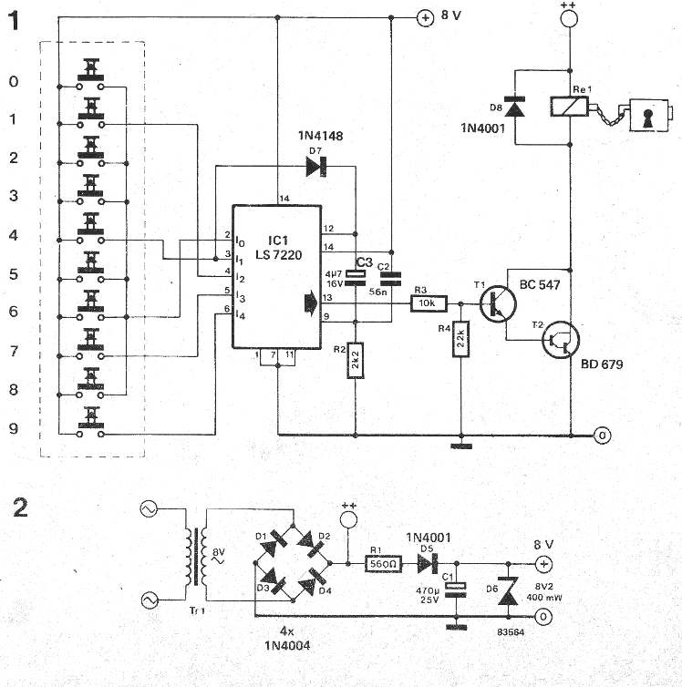
The complete circuit of the proposed door lock circuit using digital code is configured around the IC LS7220.

Its pin numbers 2 to 6 are wired across the 10 keypad button through a special arrangement so that pressing only a the selected sequence of the code on the 0 to 9 buttons activates the output of the IC.

Basically pins numbers 3 to 6 enable the correct code sequence.

In this door lock using digital code circuit the keypads can e seen attached with the IC pinouts in the format: 4179

IMG 0005

You'll also like:

  • 1.  High Voltage Alarm Circuit
  • 2.  How to Make a Simple Motorcycle Security Alarm with Tilt Sensor
  • 3.  Simple Burglar Deterrent Circuit
  • 4.  Laser Operated Security Alarm Circuit
  • 5.  Battery Low Voltage Alarm Circuit using NAND Gates
  • 6.  How to Make a Power Interruption Alarm Circuit

Tagged With: Code, Digital, Door, Lock

About Admin

Hey friends, Thanks a bunch for stopping by this site! I am an engineer with a Bachelor of Engineering in Electronics and Telecommunication. One of my passions is gathering information from all sorts of electronics books and tutorials. I then take that information and compile it into a language that is super easy to understand. My goal is to make those complex electronics circuit concepts and technical terms much more accessible for all the new and budding electronics engineers out there. I can also design customized circuit diagrams as required by the users.
If you have any questions related to this field, please do not hesitate to drop a comment! I am always here and ready to help you out with any queries you might have. I cannot wait to hear from you!

Reader Interactions

Leave a Reply Cancel reply

Your email address will not be published. Required fields are marked *

Primary Sidebar

Categories

  • 3 Phase (4)
  • 8051 Microcontroller (1)
  • Arduino (11)
  • Audio and Amplifier (102)
  • Automation (8)
  • Battery Chargers (64)
  • Bicycle Projects (4)
  • Car and Motorcycle Projects (39)
  • Datasheets (10)
  • DIY Projects (5)
  • Electrical (15)
  • Free Energy (6)
  • Games Projects (2)
  • High Voltage (14)
  • Hobby Projects (30)
  • Household Circuits (2)
  • IC 555 Circuits (4)
  • Ignition Circuits (2)
  • Indicators (50)
  • Infrared (6)
  • Inverter Circuits (29)
  • Lights and Lamps (97)
  • Medical (8)
  • Meter and Tester Circuits (38)
  • Motor Driver (17)
  • New Circuits (56)
  • Oscillators (30)
  • Pets and Pests (5)
  • Power supply (81)
  • Protection Circuits (25)
  • PWM (8)
  • Remote Control (20)
  • Security and Alarm Circuit (48)
  • Sensors and Detectors (66)
  • Signal Processor (23)
  • Solar Controller Circuits (61)
  • SSR (3)
  • Temperature Controller (20)
  • Timer (25)
  • Transformerless (7)
  • Transmitters (12)
  • Tutorials (45)
  • UPS (2)
  • Voltage Regulators (57)
  • Water Sensor and Controller (29)
  • Home
  • Privacy Policy
  • Contact
  • Disclaimer
  • Copyright

© 2025 · Making Easy Circuits