• Skip to main content
  • Skip to primary sidebar

Making Easy Circuits

Learn and build electronic circuits

You are here: Home / Sensors and Detectors / Red, Green Signal Lamp Flasher Circuit for Railways

Red, Green Signal Lamp Flasher Circuit for Railways

Last Updated on January 30, 2025 by Admin Leave a Comment

This post explains exactly how to construct a basic railway signal light that guards may use to provide handheld signals to different trains using a variety of signaling types. Mr. Danny asked for the concept.

Electrical Details

I require a railway led signaling light project layout. There must be four modes on the light. 1) Red stable 2) Steady green 3) bursts of red 4) Green blinks likewise indicate that the circuit is charged appropriately.

The setup

A straightforward IC 555 astable circuit may be used to build the suggested railway signal lamp circuit with blinking LEDs, as seen below:

Circuit Diagram

Red, Green Signal Lamp Flasher Circuit for Railways

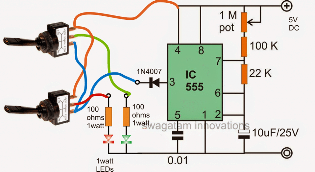
If we take a look at the diagram that is provided above we can start to understand how the circuit operates as I will explain in detail below.

Circuit Operation

The integrated circuit known as the IC 555 is set up in what is commonly referred to as its standard astable mode.

This configuration is designed specifically to generate an alternating ON and OFF potential at pin number three of the IC.

This particular IC has impressive capabilities and is rated to deliver a current of up to approximately two hundred milliamperes.

Because of this rating one watt LEDs are perfectly suitable for being connected directly to this specific pinout of the IC.

Now since these one watt LEDs are rated to handle a current of three hundred fifty milliamperes the lower amount of current that is available allows these LEDs to operate without the need for heatsinks.

However even with a current of one hundred milliamperes it can be expected that the light emitted from these LEDs will be significantly bright making them quite appropriate for the railway safety signal lamp application that has been requested.

In this setup there is a one megohm potentiometer which is utilized to adjust the flashing rate of the LEDs.

Additionally there are switches that determine the operational modes of the LEDs according to the specifications that have been requested.

It is important to note that the switches should be of the single pole double throw type and must include a center off feature.

When you toggle the relevant switches downwards it results in a constant switched ON response from the LEDs.

On the other hand if you toggle them to the lower side it allows the LEDs to flash.

The center off feature of these switches can be conveniently used for keeping the LEDs turned off when they are not needed.

To further enhance performance it is essential that the LEDs are housed inside high gloss reflector cones.

This design choice will help achieve an improved light output and will also increase the visibility range significantly.

You'll also like:

  • 1.  Automatic Day/Night Switch Circuit using Bi-Metal Strip and LDR
  • 2.  Proximity Detector Circuit – LC Tuned IC CS209
  • 3.  Inductive Non Contact Current Sensor Circuit
  • 4.  Simple PIR Water Sprinkler Circuit
  • 5.  Sound Operated Switch Circuit
  • 6.  Metal Detector Circuit using a Single IC

About Admin

Hey friends, Thanks a bunch for stopping by this site! I am an engineer with a Bachelor of Engineering in Electronics and Telecommunication. One of my passions is gathering information from all sorts of electronics books and tutorials. I then take that information and compile it into a language that is super easy to understand. My goal is to make those complex electronics circuit concepts and technical terms much more accessible for all the new and budding electronics engineers out there. I can also design customized circuit diagrams as required by the users.
If you have any questions related to this field, please do not hesitate to drop a comment! I am always here and ready to help you out with any queries you might have. I cannot wait to hear from you!

Reader Interactions

Leave a Reply Cancel reply

Your email address will not be published. Required fields are marked *

Primary Sidebar

Categories

  • 3 Phase (4)
  • 8051 Microcontroller (1)
  • Arduino (11)
  • Audio and Amplifier (102)
  • Automation (8)
  • Battery Chargers (64)
  • Bicycle Projects (4)
  • Car and Motorcycle Projects (39)
  • Datasheets (10)
  • DIY Projects (5)
  • Electrical (15)
  • Free Energy (6)
  • Games Projects (2)
  • High Voltage (14)
  • Hobby Projects (30)
  • Household Circuits (2)
  • IC 555 Circuits (5)
  • Ignition Circuits (2)
  • Indicators (50)
  • Infrared (6)
  • Inverter Circuits (29)
  • Lights and Lamps (97)
  • Medical (8)
  • Meter and Tester Circuits (38)
  • Motor Driver (17)
  • New Circuits (56)
  • Oscillators (30)
  • Pets and Pests (5)
  • Power supply (80)
  • Protection Circuits (25)
  • PWM (9)
  • Remote Control (20)
  • Security and Alarm Circuit (48)
  • Sensors and Detectors (66)
  • Signal Processor (23)
  • Solar Controller Circuits (62)
  • SSR (3)
  • Temperature Controller (20)
  • Timer (25)
  • Transformerless (7)
  • Transmitters (12)
  • Tutorials (45)
  • UPS (2)
  • Voltage Regulators (57)
  • Water Sensor and Controller (29)
  • Home
  • Privacy Policy
  • Contact
  • Disclaimer
  • Copyright

© 2025 · Making Easy Circuits