The post describes an alternator or generator power booster circuit, Let's find out more about the .

Circuit Justification
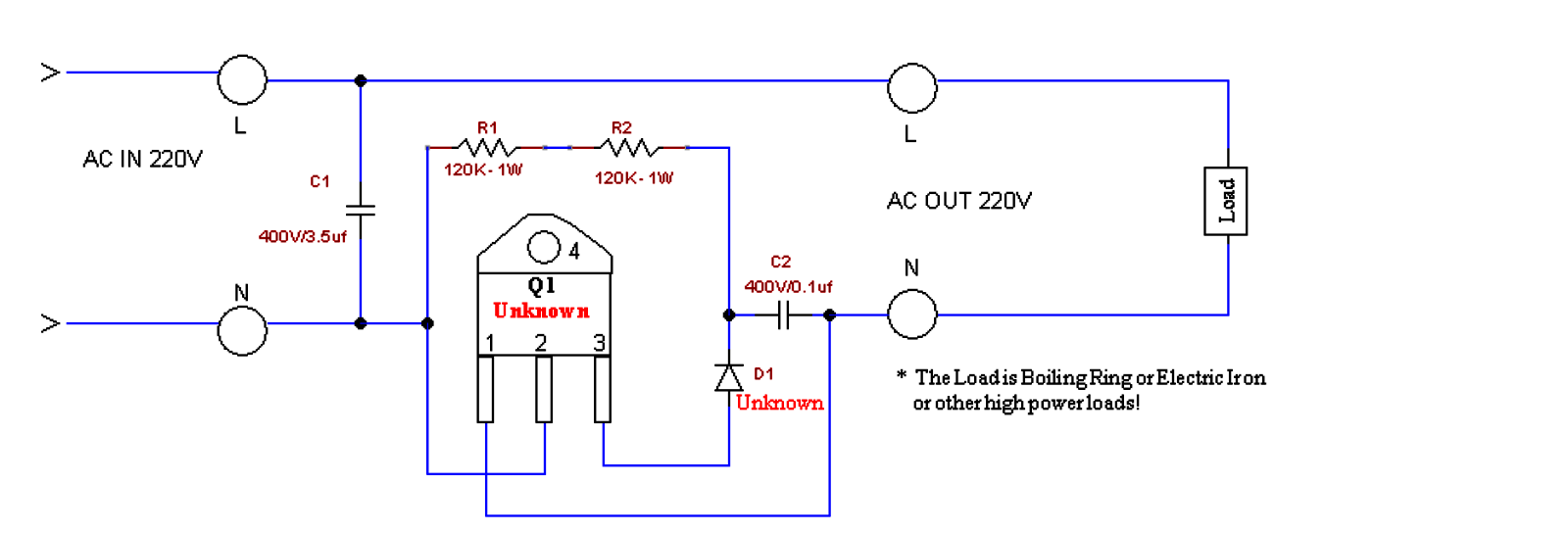
The circuit seems to be a straightforward AC voltage booster. The main part which can be to blame for providing the excess power is the high voltage capacitor C1 which charges up with each AC cycle and reverts the power by means of the switching triac into the linked load.
The load thus gets added power due to the switching high voltage capacitor by way of the triac.
The triac is usually a BTA41/600A, which replies and switches ON the moment the diac fires. The minimum voltage necessary for the diac to fire is around 30 volts.
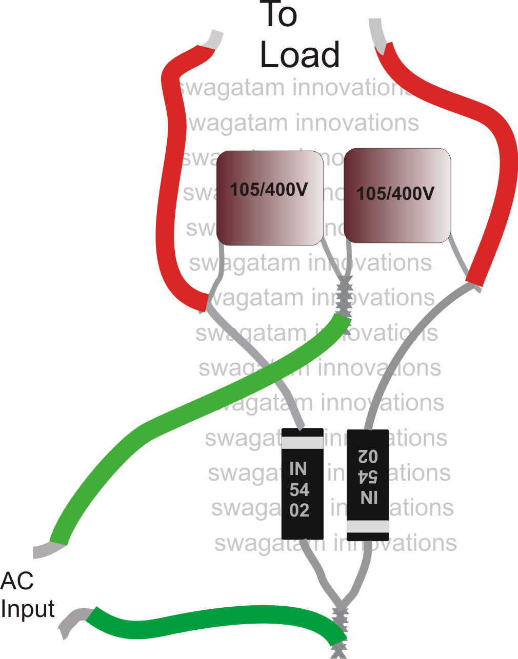
The above idea may also be used with the following circuit which happens to be less complicated than the above and is also very much cheaper.

The capacitor ratings might be altered and tried as per the load, and individual choices.
However this circuit can be utilized only for heater applications such as irons, heaters, geysers, ovens, toasters, blowers, dryers, hot air gun etc.
Please can the second circuit be used to boost inverter power?
It will only boost voltage, not power, and will work only for resistive loads..
Please how many watts is the second circuit? I build it and is not working with my soldering iron not even to talk of iron Sir. Please I need an urgent help because this is my project topic and to be submitted soon. Thanks
It is a tested design and it worked for me beautifully, my soldering iron became red hot within 1 minute.
It is nothing but a simple voltage doubler circuit.
310V x 50 mA = 15 watts
The first circuit needs clearification
OK I want to boost power from a 600watts generator to supply my electric iron and cooker what will be the rating of the diac
The 2nd circuit has zero vibration in all
Generator
The first one lacks clarity and unsure if it would work. The second one is a half-wave voltage doubler, DC output. When capacitance is small and load-current is large, the voltage will be unregulated, spiky, or contains more ripple.
That’s exactly why the second circuit is recommended for resistive loads….
I Made that second one its working, but i think the output was dc
but the voltage was up to 250v.
i have not test it with any appliances,
please should i go ahead
an test it?
yes it will be DC but 2 times more than the input AC. You can use it with resistive loads sch heaters, soldering iron, and also for electronic items such as LED bulbs but only during mains brownouts.
The circuit diagram some components values are missing pls can u help us out
Hi admin, I connected the second circuit and when I measured the output voltage I onlg received a reading only for a second. I think the capacitor I sonly charging from just a half circle. I also tested the diodes and they were working perfectly. Pls what should I do
check it with a 25 watt AC lamp and see the brightness…it will be a lot brighter compared to when it is connected to AC without this circuit..
Please the second circuit how would I know the wire that will go to life point and neutral point.
What kind of capacitors should I use to make the second circuit.
Metallized PPC
Pls can I use 105j /400v for the first circuit?
I am not sure about it
How can I get the value of the unknown?
plz how can i use transformers to boost current,any circuit for it
if you boost current, voltage will go down and vice versa
What are the numbers of unknown triac and diac on the first diagram?
you can use any triac and any diac as per your load specs…
hello admin, ive tried building the first circuit diagram and didnt get any result. please can you explain how i can really achieve this
hello mordian, the first circuit was drawn from an obscure broken sample by one of the hobbyists, so we don’t know whether it was copied correctly or not, however the second circuit was tested OK, and could be used for boosting any AC resistive load, by appropriately dimensioning the capacitor values
Pls any idea on A circuit which can be used
a transformer is the only thing which can be used for boosting voltage or current…
Pls can the first circuit be used to boost voltage for a big refrigerator which can’t just be powered by a small generator set
Not sure. but most probably it cannot be used for inductive loads
Good morning Sir, is the first circuit working? Because I designed it but the output voltage is reading 110v
Hello Patrick, the first circuit is not yet tested by me so I am not sure about it.
Can a 650watts generator be boosted to power a refrigerator?
a 650 watt generator can be directly used for powering a refrigerator….why does it need to be boosted