The introduced 3 phase VFD circuit (created by me) can be utilized for regulating the speed of any three phase brushed AC motor or perhaps a brushless AC motor.
For developing the suggested 3 phase VFD or variable frequency drive circuit the following essential circuit steps are actually required:
PWM voltage controller circuit
3 phase high side/low side H-bridge driver circuit
3 Phase generator circuit
Voltage to frequency converter circuit for producing V/Hz parameter.
Let's understand the performing particulars of the above phases by making use of the following explanation:
A basic PWM voltage controller circuit could be experienced in the diagram provided below:
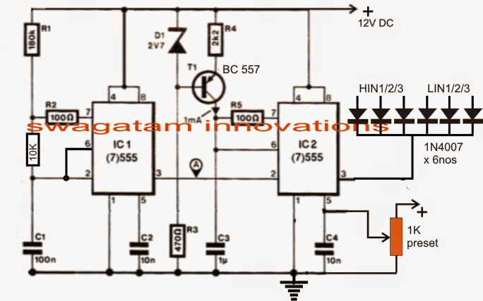
3 Phase Adjustable Frequency Drive Circuit
I have already integrated and described the working of the above PWM generator phase which happens to be essentially manufactured for producing a various PWM output across pin3 of IC2 as a reaction to the potential utilized at pin5 of the same IC.
The 1K preset demonstrated in the diagram is the RMS control knob, which might be properly modified for obtaining the preferred proportionate quantity of output voltage by means of PWMs at pin3 of IC2 for furthermore working.
This really is set to generate a respective output which might be comparable to the mains 220V or 120V AC RMS.
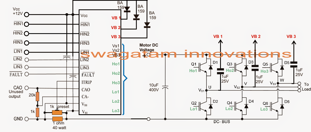
The subsequent diagram below reflects a single chip H-bridge 3 phase driver circuit implementing the IC IRS2330.
The design appears simple since many of the difficulties are taken care of by the chips in-built advanced circuitry.
A competently determined 3 phase signal is used across the HIN1/2/3 and LIN1/2/3 inputs of the IC by means of a 3 phase signal generator stage
These inputs of the IC may also be observed built-in with the above PWM output for the essential voltage regulation across the IGBTs or mosfets associated with the 3 phase motor.
This regulation will undoubtedly assist the motor to acquire the preferred speed as per the settings (via the1k preset in the first diagram).
Below diagram we imagine the needed 3 phase signal generator circuit.
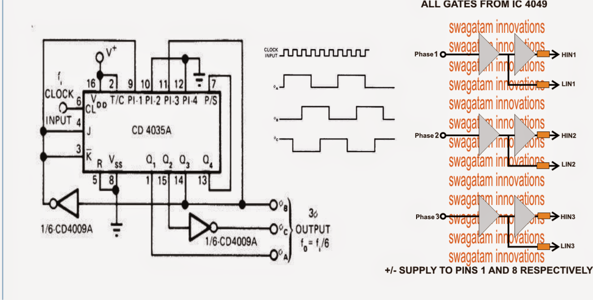
The 3 phase generator is designed around several CMOS chips CD4035 and CD4009 which produces precisely dimensioned 3 phase signals across the demonstrated pinouts.
The frequency of the 3 phase signals varies according to the given input clocks which must be 6 times the meant 3 phase signal.
Which means, if the preferred 3 phase frequency is 50 Hz, the input clock ought to be 50 x 6 = 300 Hz.
Moreover it suggests that the above clocks could possibly be diversified with the intention to vary the useful frequency of the driver IC that might could well be accountable of differing the motor operational frequency.
Nevertheless considering that the above frequency modification must be automatic as a reaction to the different voltage, a voltage to frequency converter turns into important.
The subsequent stage talks about a basic precise voltage to frequency converter circuit for the essential execution.
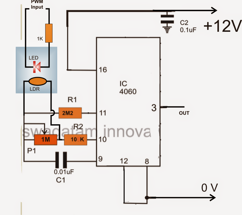
In the above voltage to frequency converter circuit a IC 4060 is utilized and its frequency dependent resistance is affected by means of a LED/LDR assembly for the meant conversions.
The LED/LDR assembly is sealed inside a light proof box, and the LDR is located across a 1M frequency dependent resistor of the IC.
Considering that the LDR/LDR reaction is rather linear, the different illumination of the LED on the LDR produces a consequently differing (rising or reducing) frequency across pin3 of the IC.
The FSD or the V/Hz range of the stage could possibly be set by properly establishing the 1M resistor or perhaps the C1 value.
The LED is voltage is produced and illuminated with the aid of the PWMs from the first PWM circuit stage.
It suggests that as the PWMs differ, the LED illumination may even vary which usually would certainly give rise to a consequently increasing or decreasing frequency at pin3 of the IC 4060 in the above diagram.
This differing frequency from the IC 4060 currently basically ought to be built-in with the 3 phase generator IC CD4035 clock input.
The above stages form the main components to create a 3 phase VFD circuit.
Currently, it might be crucial that you talk about relating to the DC BUS essential for providing the IGBT motor controllers and the establishing processes for the whole design.
The DC BUS utilized across the IGBT H-bridge rails might be acquired by rectifying the offered 3 phase mains input utilizing the following circuit configuration.
The IGBT DC BUS rails are linked across the points mentioned as "load"
3 phase DC rectifier circuit

For a single phase source the rectification might be used utilizing regular 4 diode bridge network configuration.
Tips on how to Establish the suggested 3 phase VFD circuit
It might be carried out according to the following directions:
After making use of the DC bus voltage across the IGBTs (without the motor attached) regulate the PWM 1k preset until the voltage across the rails turn out to be equivalent to the meant motor voltage features.
Subsequent regulate the IC 4060 1M preset to be able to adjust any of IC IRS2330 inputs to the needed proper frequency level according to the presented motor requirements.
After the above processes are finished, the stipulated motor might be linked and supplied with various voltage levels, V/Hz parameter and established for an automatic V/Hz procedures over the attached motor.
I tried it. Unfortunately, All (three) waveforms are same. There is no phase angle.
did you check it on a 3 phase oscilloscope?
Map inverter drive handles elctromotor 2.2kw
Thank you so much for replying .
C is between Vcc and Vss as well Vso
R the shunt of ITRIP if I am going to load 12 A
thank you a gain
you are welcome! those are not critical you can use 10uF 25V for both
Hello
have you tested the IR 2130 cct ? and are the R & C value correct to this operation?
thanks
The IR circuit is taken from the datasheet of the IC and it is tested by many other readers, which RC your referring to?
Dear Swagatam thank for this site .Kindly i was requesting for a three phase vfd circuit with an adjustable output frequency from 400hz to 1 mhz with an output of three phases.For a special project.Do you make projects on contract?In case i want that project what are the terms and conditions?How long can it take to complete it?
Regards
Eric
Thank you dear Eric,
In the above design if you apply a varying frequency between 400Hz and 1MHz at the clock input of the IC 4035, the output will operate with an identical 3 phase frequency….however I am not sure whether the respective parts are assigned to handle 1MHz or not??
I am sorry I do not make circuits practically, that’s due to my continuous involvement with website works…
Dear Swagatam
Thanks for the reply and continued support.
I need circuit ,one vfd with at least a frequency range between 1hz to at least 800khz for a test and collection of data.In your previous circuit what modification can be made to archive that?
What about using Atmel 8 bi micro controller?
Regards
Eric
Hi Eric, I am not good with microcontrollers so won’t be able to suggest much regarding that option. However in the above design you can apply the frequency from 1 Hz to 800kHz without changing anything, having said this you may have to verify each of the stages separately while building the unit.
Have you tested this circuit for hp rating and is there a diagram for the entire circuit from line to the 3 phase output
the various stages involved are tested separately and successfully, but together the whole project is yet to be tested.
good day sir, please I want to know if the circuits above can work for a three phase AC electric motors. Thanks.
Hi Obelia, it is designed for 3 phase AC motors, therefore it has to work…