• Skip to main content
  • Skip to primary sidebar

Making Easy Circuits

Learn and build electronic circuits

You are here: Home / Motor Driver / How to Build a Pedal Speed Controller Circuit for Electric Vehicles Part-1

How to Build a Pedal Speed Controller Circuit for Electric Vehicles Part-1

Last Updated on February 17, 2018 by Admin Leave a Comment

In this particular section of the post we find out about a creative technique of transforming pedal press mechanism in electric vehicles into a in the same way varying electrical signal, which can be even more useful for processing the speed control of the vehicle.
An electronic version of a pedal accelerator will mostly desire a mechanism to first transfer mechanical pressing of the pedal into a in the same way differing electrical signal, to ensure that this signal may be dealt with by means of a signal processor phase for the preferred conversion into an economical speed control of the vehicle.
A lot of principles tend to be attempted for example by utilizing a piezo load sensor, a capacitive load sensor, by a resonance sensor etc. In this post we are going to discover a considerably less complicated technique created by me which contains a LED/LDR assembly for attaining the same.
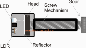
 

electronic2Bpedal2Baccelerator2Bcircuit
In the electromechanical set up demonstrated in the figure above you can easily observe the following incorporated components:
A small gear associated with a screw mechanism.
The head of the screw obtaining a white mat reflector surface
A LED/LDR assembly placed in front of the screw head.
How the Suggested mechanism functions.
The gear demonstrated in the above figure is usually to be locked with a different gear having a ratio which might be 10 times more than this gear.
The bigger gear really should be set up with the pedal mechanism such that it is linked to a rotational activity in accordance with the pressing of the pedal.
The rotational result from the gears will subsequently generate a forward motion of the screw head across the chamber where the LED/LDR assembly is situated.
The method may cause a correspondingly varying amount of shown light from the LED to be obtained by the LDR.
This varying data (by means of a varying resistance) in accordance with the pedal depression may be then provided to a signal processor circuit for enforcing the meant speed control of the specific vehicle.
Within the next submit we are going to understand the signal processor stage making use of PWM method.

You'll also like:

  • 1.  How to make a Temperature Triggered DC Fan Speed Controller Circuit
  • 2.  How to Build a 3 Phase Brushless (BLDC) Motor Driver Circuit
  • 3.  Automatic Sliding Door Circuit
  • 4.  Simple DC Motor Speed Controller Circuit
  • 5.  Protecting Motor from Overcurrent Conditions
  • 6.  Model Train Controller Circuit

About Admin

Hey friends, Thanks a bunch for stopping by this site! I am an engineer with a Bachelor of Engineering in Electronics and Telecommunication. One of my passions is gathering information from all sorts of electronics books and tutorials. I then take that information and compile it into a language that is super easy to understand. My goal is to make those complex electronics circuit concepts and technical terms much more accessible for all the new and budding electronics engineers out there. I can also design customized circuit diagrams as required by the users.
If you have any questions related to this field, please do not hesitate to drop a comment! I am always here and ready to help you out with any queries you might have. I cannot wait to hear from you!

Reader Interactions

Leave a Reply Cancel reply

Your email address will not be published. Required fields are marked *

Primary Sidebar

Categories

  • 3 Phase (4)
  • 8051 Microcontroller (1)
  • Arduino (11)
  • Audio and Amplifier (102)
  • Automation (8)
  • Battery Chargers (64)
  • Bicycle Projects (4)
  • Car and Motorcycle Projects (39)
  • Datasheets (10)
  • DIY Projects (5)
  • Electrical (15)
  • Free Energy (6)
  • Games Projects (2)
  • High Voltage (14)
  • Hobby Projects (30)
  • Household Circuits (2)
  • IC 555 Circuits (5)
  • Ignition Circuits (2)
  • Indicators (50)
  • Infrared (6)
  • Inverter Circuits (29)
  • Lights and Lamps (97)
  • Medical (8)
  • Meter and Tester Circuits (38)
  • Motor Driver (17)
  • New Circuits (56)
  • Oscillators (30)
  • Pets and Pests (5)
  • Power supply (80)
  • Protection Circuits (25)
  • PWM (9)
  • Remote Control (20)
  • Security and Alarm Circuit (48)
  • Sensors and Detectors (66)
  • Signal Processor (23)
  • Solar Controller Circuits (62)
  • SSR (3)
  • Temperature Controller (20)
  • Timer (25)
  • Transformerless (7)
  • Transmitters (12)
  • Tutorials (45)
  • UPS (2)
  • Voltage Regulators (57)
  • Water Sensor and Controller (29)
  • Home
  • Privacy Policy
  • Contact
  • Disclaimer
  • Copyright

© 2025 · Making Easy Circuits