• Skip to main content
  • Skip to primary sidebar

Making Easy Circuits

Learn and build electronic circuits

You are here: Home / Car and Motorcycle Projects / How to Make a Car Battery Voltage Monitor Circuit

How to Make a Car Battery Voltage Monitor Circuit

Last Updated on February 17, 2018 by Admin Leave a Comment

This easy 4 LED car voltmeter is made to enable us to observe the voltage level of the battery of our car at any moment, always.
To obtain the above function it has got to be positioned somewhere in the dash of the car to ensure that the group of 4 LEDs continue to be protruded, each with a label indicating the battery voltage having at that instant.
The circuit is meant for performing the following:
- 1st LED lights with 11V battery
- 1st and 2nd LEDs light with battery 12V
- 1st, 2nd and 3rd LEDs light with battery 13V
- 1st, 2nd, 3rd and 4th (all) LEDs light with battery 14V
Operational aspect of the Car Battery Voltmeter/Monitor Circuit.
When the battery voltage falls to 11 or 12 volts, it might require charging. If its around 13 volts it is in appropriate situation. At 14 volts it is completely charged. The colors of the LEDs show these position.
The main elements of the circuit are simply a couple of functional amplifiers utilized as comparators.
The inverting inputs associated with these functional are set at fixed reference voltages: 5.1, 4.8, 4.4, 4.1 utilizing zener diode D1 and resistor network: R1, R2, R3 and VR potentiometer.
The VR potentiometer is employed to create minor adjustments to the above referenced voltages, which may differs simply because the resistors are not precise values.
The battery voltage is brought to non-inverting inputs of the opamps by means of the presented voltage divider networks created by R4 and R6 terminals.
Based on the battery voltage, the voltage at the non-inverting terminal will be different and will put a high voltage level at the output of the comparator, signaling the related LED for the needed indications.


Car Battery Voltage Monitor Circuit using LEDs and IC LM324
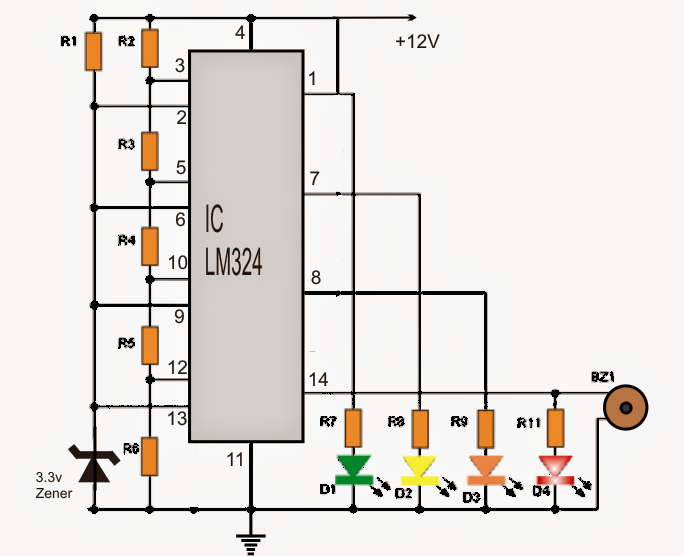
Car Battery Voltage Monitor Circuit making use of LEDs and IC LM324
Parts list for the circuit
- IC1: LM324 integrated (quad opamps in a single integrated) Circuit
- D1: 3.3V zener diode, 1/4 watt
- D2 = D3 = D4 = D5: Diodes LED (2 red, 1 yellow or amber, 1 green)
- R1 = 1K
- R2.....R6: all 1K preset
+12V: is the car battery whose voltage is usually to be felt

You'll also like:

  • 1.  Doorbell With Memory Circuit
  • 2.  Simple Digital Voltmeter Circuit
  • 3.  Making Smart Car Turn-Signals, Side-Markers, and Parking Lights
  • 4.  Simple 5 LED Music Level Indicator using a single IC
  • 5.  220 V LED Indicator Circuit
  • 6.  How To Make Battery Charging Fault Indicator Circuit

About Admin

Hey friends, Thanks a bunch for stopping by this site! I am an engineer with a Bachelor of Engineering in Electronics and Telecommunication. One of my passions is gathering information from all sorts of electronics books and tutorials. I then take that information and compile it into a language that is super easy to understand. My goal is to make those complex electronics circuit concepts and technical terms much more accessible for all the new and budding electronics engineers out there. I can also design customized circuit diagrams as required by the users.
If you have any questions related to this field, please do not hesitate to drop a comment! I am always here and ready to help you out with any queries you might have. I cannot wait to hear from you!

Reader Interactions

Leave a Reply Cancel reply

Your email address will not be published. Required fields are marked *

Primary Sidebar

Categories

  • 3 Phase (4)
  • 8051 Microcontroller (1)
  • Arduino (11)
  • Audio and Amplifier (102)
  • Automation (8)
  • Battery Chargers (64)
  • Bicycle Projects (4)
  • Car and Motorcycle Projects (39)
  • Datasheets (10)
  • DIY Projects (5)
  • Electrical (15)
  • Free Energy (6)
  • Games Projects (2)
  • High Voltage (14)
  • Hobby Projects (30)
  • Household Circuits (2)
  • IC 555 Circuits (5)
  • Ignition Circuits (2)
  • Indicators (50)
  • Infrared (6)
  • Inverter Circuits (29)
  • Lights and Lamps (97)
  • Medical (8)
  • Meter and Tester Circuits (38)
  • Motor Driver (17)
  • New Circuits (56)
  • Oscillators (30)
  • Pets and Pests (5)
  • Power supply (80)
  • Protection Circuits (25)
  • PWM (9)
  • Remote Control (20)
  • Security and Alarm Circuit (48)
  • Sensors and Detectors (66)
  • Signal Processor (23)
  • Solar Controller Circuits (62)
  • SSR (3)
  • Temperature Controller (20)
  • Timer (25)
  • Transformerless (7)
  • Transmitters (12)
  • Tutorials (45)
  • UPS (2)
  • Voltage Regulators (57)
  • Water Sensor and Controller (29)
  • Home
  • Privacy Policy
  • Contact
  • Disclaimer
  • Copyright

© 2025 · Making Easy Circuits