This very simple circuit enable you to imitate the operation of a music box. The number of notes may be confined to 10 at the most, thereby can result in creating a basic track.
The circuit utilizes two well-liked incorporated circuits: The timer 555 and 4017 decade counter
Operation of the circuit of music box could be figured out provided below:
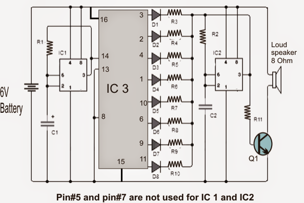
The left 555 is employed as clock generator for the 4017 decade counter.
The operating frequency of the clock could be modified and adjusted by a way of changing the value resistor R1 or by switching it with a potentiometer 50K providing a 1K series resistor of 1K in order that you don't accidentally move the pot to short the supply with pin7 of the IC.
When the left IC 555 clock rate is varied, the speed of the 4017 output sequence is changed consequently which causes the musical sounds of the box
The above output signal 555 provides the clock input of CD4017 which produces 10 active outputs (high voltage) sequentially you start with 0 and ending exit at junction 9.
As could be used in the diagram the outputs 3 and 6 of the 4017 outputs are not applied. This is exactly particularly designed in order to generate spaces of silence in the melody from the music box.
Each CD4017 output might be noticed feeding a series diode with a resistor which effectively links the corresponding resistor in series with the second resistor R2 555.
The above arrangement in conjunction with the capacitor C2, force the second 555 to oscillate at a certain predetermined frequency.
The moment a CD4017 output is started, the right hand side 555 oscillates at a frequency prefixed by the set R (of the outputs of 4017), in conjunction with R2 and C2. The moment the complete phase of the 4017 outputs are applied, the IC is reset and process is repeated.
To operate the speaker transistor Q1 has to pass the saturation cutting frequency ranges to which the second 555 is configured at.
As can be watched, the project helps us to experience and gain a sequenced set of notes in accordance with the choice of the user. Experimenting with the values of the resistors in series with the diodes could be wise to commence with.
Additionally you can research and alter the spaces and location of the "silences", by randomly leaving or picking from the other pins of the 4017 outputs.
The music box circuit is driven with 9 volt PP3 battery or from a 9V AC/DC adapter.
Simple Music Box circuit
Bill Of Materials for the music box circuit
- IC1 = IC2: 555 timer
- IC3: CD4017 decade counter
- Q1: TIP29 NPN bipolar transistor or the like
- R1 = R2: 33K resistor
- R3 = R5 = R9: 10K resistors
- R4 = R7 = R10: 15K resistors
- R6 = R8: 22K resistors
- R11: 470 ohm resistor
- C1: 10uF/25V
- C2: capacitor of 10nF
- D1 = D2 = D3 = D4 = D5 = D6 = D7 = D8: diode 1N4148 or equivalent
- LS: Miniature speaker 8 ohms.
Hello,
You mentioned that pin 5 and 7 are not used for both the NE555, but I also miss them on the 4017. This means 3 beats, pauze, 2 beats, pauze and 3 bits. In a sequence of 2 x 4 beats this doesn’t sound logic to me. Why not pin 3,2,4,7 and pin 10,1,5,6 to the array diodes. pin 9 can reset the circuit.
I don ‘t get it.
Interesting project, I must say.
Regards,
Marcel
Hi, actually both the 555 ICs are wired as astable multivibrators, so you can wire them as you like as long as they work like astable oscillators. The 4017 pinouts can be experimented and adjusted as per individual preferences.