• Skip to main content
  • Skip to primary sidebar

Making Easy Circuits

Learn and build electronic circuits

You are here: Home / Power supply / 220V Power Supply Circuit using MJE13005 without Transformer

220V Power Supply Circuit using MJE13005 without Transformer

Last Updated on January 28, 2025 by Admin Leave a Comment

The article that you are about to read introduces a really straightforward and uncomplicated circuit for a transformerless power supply that operates on a low current from a 220 V mains source.

This circuit utilizes a budget-friendly MJE13005 transistor along with a handful of other passive electronic components.

If you take a look at the circuit diagram provided you will see that the design is incredibly simple and easy to follow.

How It Works

In this setup, the key player is the transistor known as T1 which is actually a high voltage NPN transistor called MJE13005. This component acts as the main active element within the circuit.

The other components in the circuit are arranged specifically to support T1's operation and to ensure everything runs smoothly and stably.

To break it down further, here are some important points to understand how this circuit functions:

The mains input is connected across D2 and the negative line of the entire circuit.

D2 has the job of rectifying the alternating current (AC) from the mains, while C1 works to filter it down to reasonable levels.

R1 is there to limit the current to acceptable levels so that it can provide the necessary base bias for T1.

After R1, C2 comes into play to offer additional filtering for the voltage that has been generated.

D1 serves as a clamp for the base voltage at T1 keeping it at 24V. This means that no matter what happens, the maximum output voltage will never go beyond this threshold.

There is also a mirror voltage produced at the output that matches the zener value. However thanks to R2, this response can be adjusted.

By tweaking R2 you can effectively change the zener voltage anywhere from zero all the way up to its maximum value of 24V.

As a result you can get an output that varies from zero volts up to 24 volts.

However it is essential to note that since we are measuring voltage across the emitter and ground of the transistor, the current is kept at very modest levels—specifically around 25mA.

That being said, you can increase the zener voltage as much as you want.

WARNING: This entire circuit is not isolated from mains AC power. Therefore it can be extremely hazardous to touch while it is powered on and uncovered. Please ensure that you take all necessary precautions when handling this circuit.
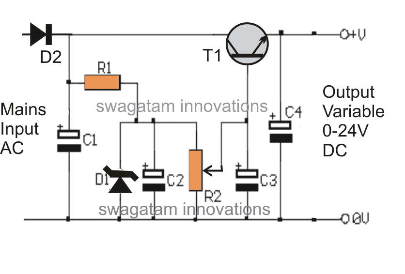
transformerlesspowersupplycircuitusingmje13005

Parts List

ComponentValue/Specification
R1100 kΩ
R210 kΩ POT (Potentiometer)
C14.7 µF / 300 V
C210 µF / 100 V
C3, C4100 µF / 30 V
D124 V, 1 WATT Zener Diode
D21N4007
T1MJE13005

You'll also like:

  • 1.  High Voltage Regulated Power Supply Circuit with Over Current Protection
  • 2.  How to Calculate SMPS Transformer
  • 3.  Simplest Variable Power Supply Circuit
  • 4.  +/- 15V Dual Regulated Power Supply Circuit
  • 5.  How to Build a 0 to 50V, 0 to10amp Variable Dual Power Supply Circuit
  • 6.  1A Voltage Regulator better than 7805, 7812

About Admin

Hey friends, Thanks a bunch for stopping by this site! I am an engineer with a Bachelor of Engineering in Electronics and Telecommunication. One of my passions is gathering information from all sorts of electronics books and tutorials. I then take that information and compile it into a language that is super easy to understand. My goal is to make those complex electronics circuit concepts and technical terms much more accessible for all the new and budding electronics engineers out there. I can also design customized circuit diagrams as required by the users.
If you have any questions related to this field, please do not hesitate to drop a comment! I am always here and ready to help you out with any queries you might have. I cannot wait to hear from you!

Reader Interactions

Leave a Reply Cancel reply

Your email address will not be published. Required fields are marked *

Primary Sidebar

Categories

  • 3 Phase (4)
  • 8051 Microcontroller (1)
  • Arduino (11)
  • Audio and Amplifier (102)
  • Automation (8)
  • Battery Chargers (64)
  • Bicycle Projects (4)
  • Car and Motorcycle Projects (39)
  • Datasheets (10)
  • DIY Projects (5)
  • Electrical (15)
  • Free Energy (6)
  • Games Projects (2)
  • High Voltage (14)
  • Hobby Projects (30)
  • Household Circuits (2)
  • IC 555 Circuits (5)
  • Ignition Circuits (2)
  • Indicators (50)
  • Infrared (6)
  • Inverter Circuits (29)
  • Lights and Lamps (97)
  • Medical (8)
  • Meter and Tester Circuits (38)
  • Motor Driver (17)
  • New Circuits (56)
  • Oscillators (30)
  • Pets and Pests (5)
  • Power supply (80)
  • Protection Circuits (25)
  • PWM (9)
  • Remote Control (20)
  • Security and Alarm Circuit (48)
  • Sensors and Detectors (66)
  • Signal Processor (23)
  • Solar Controller Circuits (62)
  • SSR (3)
  • Temperature Controller (20)
  • Timer (25)
  • Transformerless (7)
  • Transmitters (12)
  • Tutorials (45)
  • UPS (2)
  • Voltage Regulators (57)
  • Water Sensor and Controller (29)
  • Home
  • Privacy Policy
  • Contact
  • Disclaimer
  • Copyright

© 2025 · Making Easy Circuits