• Skip to main content
  • Skip to primary sidebar

Making Easy Circuits

Learn and build electronic circuits

You are here: Home / Water Sensor and Controller / ULN2003 Water Level Controller Circuit

ULN2003 Water Level Controller Circuit

Last Updated on November 17, 2024 by Admin Leave a Comment

The ULN2003 is a chip which contains seven separate sections, each made up of special transistors called Darlington pairs. These pairs are designed to manage moderate amounts of electrical current, up to 500 milliamperes, and can work with voltages as high as 50 volts.

You can use the ULN2003 to create a complete and automated system which controls and indicates the water level across seven stages, as demonstrated in the example provided.

automatic water level controller circuit diagram using IC ULN2003

Circuit working

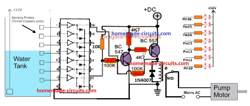
The ULN2003 chip has a special circuit connected to its top and bottom pins that controls turning on and off a relay and a motor pump.

Imagine the water level is low, not touching the pin7 sensor. Then pin10 doesnt do anything, which lets electricity flow to BC547 through a resistor.

This turns on another BC557, that keeps both parts active through a connection with a 100K resistor.

This also turns on the relay, which starts the motor pump, and water begins to fill the tank.

Even when the water goes above the pin7 sensor, it does not stop the relay because of the way the BC547 and BC557 are connected with the 100K resistor.

When the water level gets high enough to touch the top sensor, pin1 of the ULN2003, it triggers pin16 to change, which stops the electricity flow to the BC547.

This turns off the relay and the motor pump, stopping the water flow.

You'll also like:

  • 1.  Simple Water Sensor Circuit with Alarm
  • 2.  Simplest Water Level Indicator Circuit using Transistor BC547
  • 3.  Automatic Plant Irrigation Circuit
  • 4.  Circuit to Control Two Submersible Pumps Alternately
  • 5.  Water Level Controller Circuit using only Transistors
  • 6.  Simple Water Level Alarm Circuit using IC 555

About Admin

Hey friends, Thanks a bunch for stopping by this site! I am an engineer with a Bachelor of Engineering in Electronics and Telecommunication. One of my passions is gathering information from all sorts of electronics books and tutorials. I then take that information and compile it into a language that is super easy to understand. My goal is to make those complex electronics circuit concepts and technical terms much more accessible for all the new and budding electronics engineers out there. I can also design customized circuit diagrams as required by the users.
If you have any questions related to this field, please do not hesitate to drop a comment! I am always here and ready to help you out with any queries you might have. I cannot wait to hear from you!

Reader Interactions

Leave a Reply Cancel reply

Your email address will not be published. Required fields are marked *

Primary Sidebar

Categories

  • 3 Phase (4)
  • 8051 Microcontroller (1)
  • Arduino (11)
  • Audio and Amplifier (102)
  • Automation (8)
  • Battery Chargers (64)
  • Bicycle Projects (4)
  • Car and Motorcycle Projects (39)
  • Datasheets (10)
  • DIY Projects (5)
  • Electrical (15)
  • Free Energy (6)
  • Games Projects (2)
  • High Voltage (14)
  • Hobby Projects (30)
  • Household Circuits (2)
  • IC 555 Circuits (4)
  • Ignition Circuits (2)
  • Indicators (50)
  • Infrared (6)
  • Inverter Circuits (29)
  • Lights and Lamps (97)
  • Medical (8)
  • Meter and Tester Circuits (38)
  • Motor Driver (17)
  • New Circuits (56)
  • Oscillators (30)
  • Pets and Pests (5)
  • Power supply (81)
  • Protection Circuits (25)
  • PWM (8)
  • Remote Control (20)
  • Security and Alarm Circuit (48)
  • Sensors and Detectors (66)
  • Signal Processor (23)
  • Solar Controller Circuits (61)
  • SSR (3)
  • Temperature Controller (20)
  • Timer (25)
  • Transformerless (7)
  • Transmitters (12)
  • Tutorials (45)
  • UPS (2)
  • Voltage Regulators (57)
  • Water Sensor and Controller (29)
  • Home
  • Privacy Policy
  • Contact
  • Disclaimer
  • Copyright

© 2025 · Making Easy Circuits