• Skip to main content
  • Skip to primary sidebar

Making Easy Circuits

Learn and build electronic circuits

You are here: Home / Hobby Projects / Keyboard Beep Circuit

Keyboard Beep Circuit

Last Updated on January 10, 2018 by Admin Leave a Comment

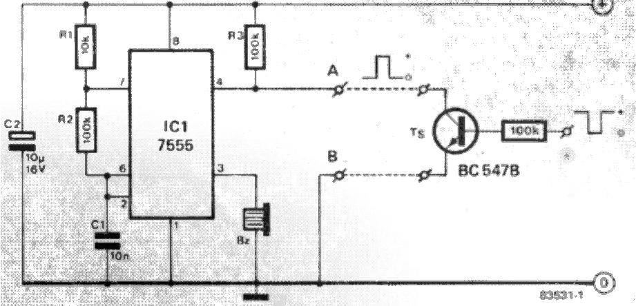
There are many situations where an audible indication for a button pressed would be very useful. Two particular cases are: a morse key, where it is otherwise impossible to know that the key has been operated, and an ASCII keyboard. This circuit is based on a 7555 timer IC (the CMOS version of the well known 555) which is connected as an astable multivibrator (ANIV). Its output is a square wave at a frequency of about 700 Hz and is used to drive* a small buzzer. The circuit will be prevented from oscillating if pin 4 of the IC is taken to 0 V, in other words, a short between points A and B in the circuit diagram.

As mentioned, the key bleep is ideal for use as a key push indicator with the ASCll keyboard. In this case a tone will be produced each time the key is pressed making it unnecessary to continually look at the screen to verify correct operation Don't worry, only one key bleep circuit is needed, not one for each key of the keyboard! The circuit can be controlled by the strobe pulse which can, of course, be either a logic ’1’ or a logic 'O’. if it is a '1’ the strobe can be connected directly to point A. lf on the other hand, it- is a 'O' then the transistor stage TS y will have to be connected between points A and B. The strobe output is then- fed directly to the base of transistor `l'S. If the circuit is to be used with ya morse key,"the transistor stage TM is required. The emitter and collec- tor of the transistor are connected to points A and B and the key is placed between its base and 0 V.


key bleep key bleep1

You'll also like:

  • 1.  Simple Crystal Tester Circuit
  • 2.  20 Best IC 741 based DIY Circuits
  • 3.  Simple SCR Circuits
  • 4.  Car Chasing LED Arrow Turn Signal Indicator Circuit
  • 5.  Coffee Temperature Indicator Circuit
  • 6.  Simple Multivibrator Circuit Projects – Astable, Bistable, Monostable

About Admin

Hey friends, Thanks a bunch for stopping by this site! I am an engineer with a Bachelor of Engineering in Electronics and Telecommunication. One of my passions is gathering information from all sorts of electronics books and tutorials. I then take that information and compile it into a language that is super easy to understand. My goal is to make those complex electronics circuit concepts and technical terms much more accessible for all the new and budding electronics engineers out there. I can also design customized circuit diagrams as required by the users.
If you have any questions related to this field, please do not hesitate to drop a comment! I am always here and ready to help you out with any queries you might have. I cannot wait to hear from you!

Reader Interactions

Leave a Reply Cancel reply

Your email address will not be published. Required fields are marked *

Primary Sidebar

Categories

  • 3 Phase (4)
  • 8051 Microcontroller (1)
  • Arduino (11)
  • Audio and Amplifier (102)
  • Automation (8)
  • Battery Chargers (64)
  • Bicycle Projects (4)
  • Car and Motorcycle Projects (39)
  • Datasheets (10)
  • DIY Projects (5)
  • Electrical (15)
  • Free Energy (6)
  • Games Projects (2)
  • High Voltage (14)
  • Hobby Projects (30)
  • Household Circuits (2)
  • IC 555 Circuits (5)
  • Ignition Circuits (2)
  • Indicators (50)
  • Infrared (6)
  • Inverter Circuits (29)
  • Lights and Lamps (97)
  • Medical (8)
  • Meter and Tester Circuits (38)
  • Motor Driver (17)
  • New Circuits (56)
  • Oscillators (30)
  • Pets and Pests (5)
  • Power supply (80)
  • Protection Circuits (25)
  • PWM (9)
  • Remote Control (20)
  • Security and Alarm Circuit (48)
  • Sensors and Detectors (66)
  • Signal Processor (23)
  • Solar Controller Circuits (62)
  • SSR (3)
  • Temperature Controller (20)
  • Timer (25)
  • Transformerless (7)
  • Transmitters (12)
  • Tutorials (45)
  • UPS (2)
  • Voltage Regulators (57)
  • Water Sensor and Controller (29)
  • Home
  • Privacy Policy
  • Contact
  • Disclaimer
  • Copyright

© 2025 · Making Easy Circuits