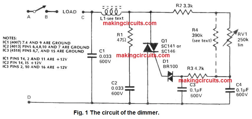
The circuit for any light dimmer is simply not complicated, as will probably be noticed through Fig. 1, nor are the parts all of that costly.
The light dimmer circuit beats a negative aspect in most of the commercial models: the Triac is secured towards line transients.
Several versions usually do not occur till the control is turned above half way, still current continues to be drawn; in our circuit the light occurs nearly at lowest setting.
An strange capability is additionally integrated within the layout which often a few readers may desire to take benefit from. A light dimmer is designed for use along with a Television set as none watching in full light or total darkness is extremely pleasing.
The light dimmer circuit is so organized that the switch may also manage a load that is not regulated by the dimmer circuitry. Hence, the television could be turned on making use of the unit, however just the light will likely be managed.
A similar set up furthermore enables us to manage just one light, departing others not affected. The unit will certainly manage 500W as demonstrated, although with a few adjustments can be simply tailored to regulate 1kW.
The choke L1 is comprised from the bit of ferrite rod, 1/4" diameter and 11/4" long, wound with 55 converts of 28 s.w.g. enameled copper wire, wound firmly and secured each and every end by a strip of adhesive tape.
For all those desperate to utilize the unit at 1kW it is crucial, for security factors, to employ a different switch from that within the pot. The right heatsink may also be essential on the Triac and also the wire gauge on L1 needs to be somewhat larger: 24 or 26 s.w.g.
The very best disadvantage while using the greater power is the fact RFI could be bothersome.
While used in combination with a reduce load, the radio disturbance is extremely minimal and may not possible be detected 12" from the prototype, despite the radio's ferrite rod in line while using choke.
Well before installing the unit, it is really worth testing on the bench, utilizing a table lamp as a load.
Link this the following. Terminal A: power live, Terminals B and C: load, Terminal D: power neutral. If almost all is perfect, the unit could be designed in place of an advanced switch built in a box.
In very shallow boxes, generally there might not be room for the unit but extension moldings are accessible through the similar folks who provide switch plate itself.
If the feature for switching an uncontrolled load is not really needed (i.e. utilizing it traditionally), a jumper wire needs to be installed amongst Terminals B and C and the two wires which usually hook up to the switch that the light dimmer eliminates could be linked to A and D.
How it Works
Just like virtually all advanced light dimmer circuits, this method incorporates a Triac for the power control.
A Triac could be considered to be an electronic switch which is switched on with a pulse at a established time in every half cycle and switches off instantly at the end of the half cycle.
Control of the Triac is of the easy resistor/capacitor and diac system. By differing the resistance of potentiometer RV1, the time constant of RV1/C4 replace the phase.
The pulse in the junction RV1/ C4 is transferred to the Diac via restricting resistor R3. The Diac is attached to the gate of the Triac and as the Diac is actually a bidirectional diode, both the positive and negative pulses are placed on the gate.
Capacitor C1 and choke L1 are for controlling RFI while R1 and C2 are employed for transient reductions. Resistor R4 is installed in order to permit complete control over light with the help of RV1.
The optimal value for RV1 is 150k ohms but since this value is practically difficult to acquire, it is added in parallel through R4 to provide efficiently this value.
Leave a Reply