The second theory will teach us the way to use the IC LM3915 to create a bicycle speedometer.
Cycling a bicycle over a rough track might cause oscillations and tremors, something the analog voltmeter depicted in the above design may be susceptible to.
The meter coil could suffer harm as a result of this.
This implies that the equipment may become incredibly dependable and fail-proof provided the meter might be swapped out for a digital or solid-state device.
An excellent solid-state substitute for showing the speed would seem to be a 10-LED bar graph display based on the LM3915.
As everyone is aware, the IC LM3915 is a dot/bar mode LED driver IC with 10 outputs.
Pin #5 on this integrated circuit will receive a fluctuating voltage input, which it will then translate into a progressively changing up/down logic across its output pins.
Contingent upon the voltage provided at its input pin #5, LEDs linked across its output pins glow in a pattern that rises and falls successively.
The image that follows illustrates way the bicycle speed may be indicated by utilizing this IC include the following characteristics:
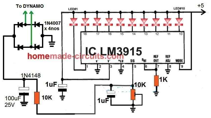
The wiring of the IC LM3915 to transform the dynamo's voltage changes into a sequenced LED bar graph screen is shown in the above image.
A handful of LEDs on the left-hand side are going to be lit up at modest speeds; when the bike speed rises, additional LEDs are going to glow up from left to right eventually all of the LEDs are lit up at the top speed.
The LED bar graph's spectrum may be calibrated by adjusting the 10K preset to ensure that each of the 10 LEDs only light up once the bicycle is traveling at its fastest potential speed.
The below shown resistive divider formula may be used to substitute a fixed resistor for the 10K preset:
Vout = Vin x R2 / (R1 + R2)
In this case, R1 is the value of the 10K resistor that is visible on the circuit's left side.
Instead of using the 10K setting, R2 is thought to be a permanent resistor.
The highest voltage needed at pin #5 is called Vout, and it should be 200 mV, or 0.2 V.
Vin is the highest voltage that the dynamo can produce to reach the 200 mV at pin #5 of the integrated circuit.
The Circuit's Operation
You must ride with a dynamo mounted on your bike in order to take advantage of this LM3915-based bicycle speed display circuit.
The dynamo wires must then be connected to the circuit's bridge rectifier, as seen in the diagram above.
Because the dynamo's output current is an AC (alternating current), that must be transformed to DC before being applied to the LM3915 circuit, a bridge rectifier is necessary.
A 10 K preset is used to provide the rectified dynamo AC to pin #5 of the LM3915 for the required sensing.
Since the LM3915 is in- house programmed for sensing a maximum operating range of 200 mV at its pin#5, the 10K preset functions as a voltage divider network, ensuring that the maximum DC from the dynamo is suitably stepped down to 200 mV.
All of the IC's outputs turn on, causing all of the attached LEDs to illuminate while pin #5 detects an effective voltage of 200 mV.
Methods for Calibration
As previously mentioned, the circuit may be calibrated using the 10K setting at pin #5 of the IC in the way shown below.
Begin paddling as fast as you can after putting your bike on stand.
At the same time, change the preset such that the tenth LED only starts to light up when the bicycle wheel rotates to its maximum.
Based on the paddling frequency and the associated dynamo voltage, you would immediately observe the LEDs gradually turning off individually until they become at a reduced level if you decrease the paddling pace.
Every single one of the LEDs is expected nearly shut off should you gradually lower the paddling movement to the lowest possible level.
Leave a Reply