Let's get started now to examine the implementation of a magnetic sensor-based device for measuring bicycle speed over a certain meter.
The illustration below illustrates how to mount the magnet and either the hall effect sensor or the reed switch sensor on the bicycle's frame and front wheel. The magnetic sensor may be a reed switch or a hall effect sensor.
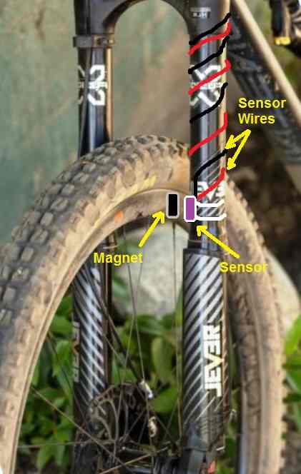
As seen in the above diagram, the sensor gadget is mounted on the bicycle's fork, and a permanent magnet is fastened to the hub of the frame.
Because both components are mounted face to face, the magnet and sensor intersect against one another with each wheel revolution, allowing the magnet's magnetic field to penetrate the sensor.
Which indicates that the sensor may react to the magnetic field cutting across it on each entire revolution by producing an electrical pulse at its output.
This indicates that the frequency of the sensor's signals will correspond to the wheel's revolutions.
To obtain the appropriate speed measurement on a meter, those signals must be sent into a 555 monostable circuit for processing. The scheme in question may be seen in the image below:
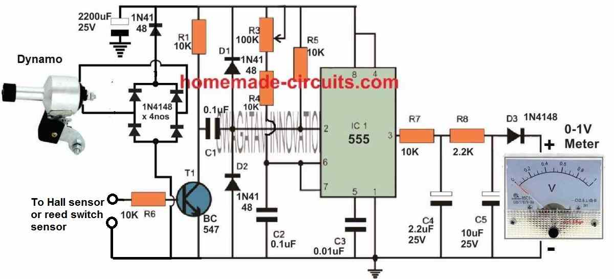
Every time the wheel turns, the magnet causes the hall effect to be established. As a result, an electrical pulse is produced at the hall sensor's output and sent to the BC547 transistor's base.
Therefore, the transistor turns on and off, which activates the IC 555 frequency to voltage converter. This causes the 555's pin #3 output to produce pulses that are the right size and match the pulses from the magnetic sensor.
When the bicycle's acceleration rises, the pulse's rate goes up as well. On the other hand, when the bicycle's speed drops, the IC 555 output's pulse rate becomes progressively smaller.
This fluctuating pulse rate that occurs at the 555's pin #3 output is routed into an integrator circuit made up of R7, R8, C4, and C5, which suitably transforms the fluctuating pulse frequency into a DC voltage that increases or decreases proportionally.
A voltmeter receives this DC voltage and converts the fluctuating pulses into a voltage readout that is exactly proportional to the bicycle's speed.
The meter is calibrated using Pot R3, which may also be a preset, to ensure that it reads a complete scale deflection at the highest possible dynamo voltage.
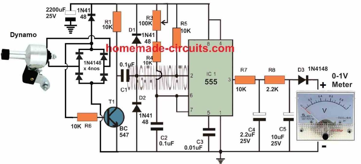
Right away hooking the 555 circuit to the dynamo regardless of a magnetic sensor
The following graphic illustrates the way to immediately. setup the dynamo outputs with the 555 input for those who find the hall effect sensor technique to be too intricate and disorganized.
The total quantity of AC cycles from the dynamo changes correspondingly with the bicycle's speed.
A bridge rectifier transforms the dynamo's fluctuating AC into DC pulses, which are then applied to the BC547's base.
The IC 555 monostable, that is triggered by the BC547, transforms the DC pulses from the dynamo into a suitable amount of ON/OFF signals at its output pin #3.
As mentioned earlier, an integrator (R7, R8, C4, C5) receives the IC 555's output and transforms the ON/OFF signals into a continuously fluctuating DC before being sent to a voltmeter.
The voltmeter shows the fluctuating DC, which is closely correlated with the bicycle's speed.
Leave a Reply