• Skip to main content
  • Skip to primary sidebar

Making Easy Circuits

Learn and build electronic circuits

You are here: Home / Remote Control / How to Make a Remote Controlled Pulley Hoist Mechanism Circuit Part-1

How to Make a Remote Controlled Pulley Hoist Mechanism Circuit Part-1

Last Updated on February 17, 2018 by Admin Leave a Comment

The submit talks about a self locking worm gear system for hoisting heavy loads by means of an electrical motor. The major function of the system being its self locking in an event of a motor malfunction.
The asked for concept appears more mechanical by nature than electronic, so it turns into crucial to talk about the mechanical portion elaborately first.
The offered remote managed bicycle hoist mechanism requires one essential function to be contained in the system, which can be undoubtedly essential for most pulley based hoist mechanisms, it's the self locking feature to stop reverse unrolling of the pulley in an event of a motor breakdown.
An extremely useful method of applying the self locking characteristic is as simple as using a worm gear system, as might be observed in the image below.

self2Blocking2Bpulley2Bgear2Bmechnaism
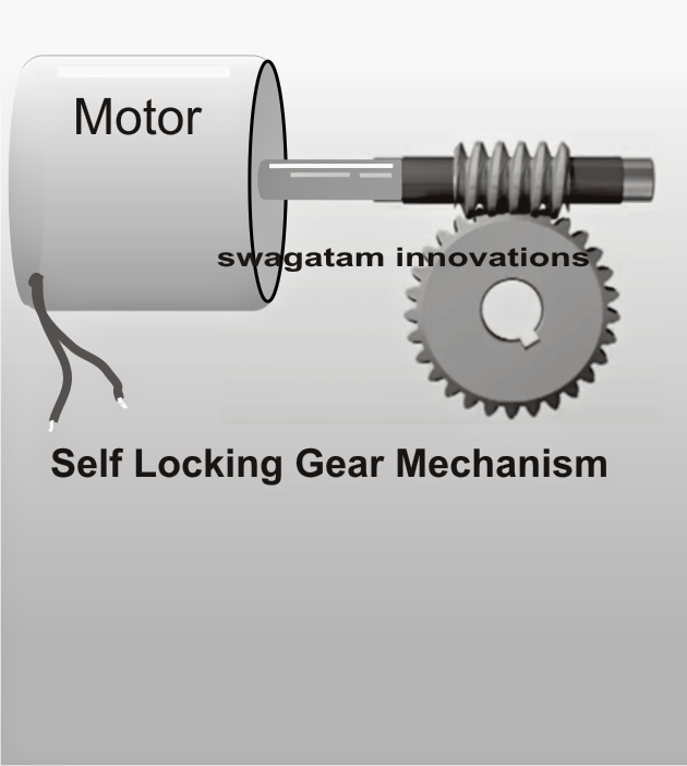
Here we observe a horizontal spiral drill bit formed shaft with its teeth locked within the teeth of a normal circular gear wheel. Now, as the spiral gear is rotated by way of a motor its teeth tend to push and roll in the forward motion pushing the teeth of the circular gear in an exact direction leading to a synchronized rotation of the lower circular gear.
The circular gear is a common which is often used for raising or moving the load and in case the motor goes wrong because of power failure or any other interruption, the spiral gear makes certain that the circular gear teeth get locked across the spiral gear teeth and evolves into virtually motionless under such circumstances.
This theory is exactly what can make a worm gear system recommended for the suggested bicycle hoist mechanism.
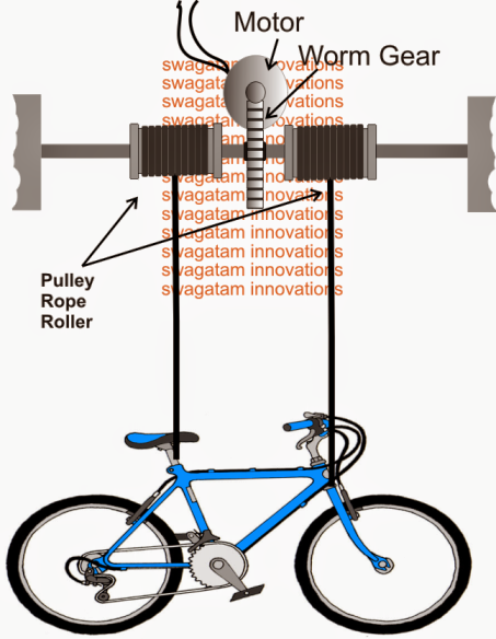
The following diagram exhibits to the technique wherein the above described worm gear mechanism might be executed in between parallel supports and with the aid of two adjacent rope and pulley assembly.
As per a visual demonstration it might be observed that whenever the motor is actuated, the gear assembly begins moving in a particular fixed direction such that the load is pulled upwards by means of coiling of the rope around the two adjacent pulleys, the reverse occurs when the motor direction is flipped.
The central rod which can be noticed supported (pivoted) over firm structures on either side ought to be improved with sealed ball bearing rings to be able to allow a smooth rotation of the whole system.

rope2Bpulley2Bmechanism
The NEXT publish will give details of ways the above mechanical design could possibly be regulated by way of a RF remote control unit

You'll also like:

  • 1.  How to build a Infrared Remote Control Security Lock Circuit for Automotive Applications
  • 2.  GSM based Irrigation Circuit using Cellphone missed Calls and Arduino
  • 3.  Wireless Lamp using an RF Disturbance Circuit
  • 4.  IR Remote Controlled Door Lock Circuit
  • 5.  Remote Control Activated Water Pump Controller Circuit
  • 6.  Flashlight Controlled Remote Control Switch Circuit

About Admin

Hey friends, Thanks a bunch for stopping by this site! I am an engineer with a Bachelor of Engineering in Electronics and Telecommunication. One of my passions is gathering information from all sorts of electronics books and tutorials. I then take that information and compile it into a language that is super easy to understand. My goal is to make those complex electronics circuit concepts and technical terms much more accessible for all the new and budding electronics engineers out there. I can also design customized circuit diagrams as required by the users.
If you have any questions related to this field, please do not hesitate to drop a comment! I am always here and ready to help you out with any queries you might have. I cannot wait to hear from you!

Reader Interactions

Leave a Reply Cancel reply

Your email address will not be published. Required fields are marked *

Primary Sidebar

Categories

  • 3 Phase (4)
  • 8051 Microcontroller (1)
  • Arduino (11)
  • Audio and Amplifier (102)
  • Automation (8)
  • Battery Chargers (64)
  • Bicycle Projects (4)
  • Car and Motorcycle Projects (39)
  • Datasheets (10)
  • DIY Projects (5)
  • Electrical (15)
  • Free Energy (6)
  • Games Projects (2)
  • High Voltage (14)
  • Hobby Projects (30)
  • Household Circuits (2)
  • IC 555 Circuits (5)
  • Ignition Circuits (2)
  • Indicators (50)
  • Infrared (6)
  • Inverter Circuits (29)
  • Lights and Lamps (97)
  • Medical (8)
  • Meter and Tester Circuits (38)
  • Motor Driver (17)
  • New Circuits (56)
  • Oscillators (30)
  • Pets and Pests (5)
  • Power supply (80)
  • Protection Circuits (25)
  • PWM (9)
  • Remote Control (20)
  • Security and Alarm Circuit (48)
  • Sensors and Detectors (66)
  • Signal Processor (23)
  • Solar Controller Circuits (62)
  • SSR (3)
  • Temperature Controller (20)
  • Timer (25)
  • Transformerless (7)
  • Transmitters (12)
  • Tutorials (45)
  • UPS (2)
  • Voltage Regulators (57)
  • Water Sensor and Controller (29)
  • Home
  • Privacy Policy
  • Contact
  • Disclaimer
  • Copyright

© 2025 · Making Easy Circuits