• Skip to main content
  • Skip to primary sidebar

Making Easy Circuits

Learn and build electronic circuits

You are here: Home / Power supply / Simple 12V 500mA SMPS Circuit

Simple 12V 500mA SMPS Circuit

Last Updated on November 17, 2024 by Admin 10 Comments

I endeavored to develop a simple 12V 500mA SMPS circuit. It makes use of an built-in circuit TNY267P of a sequence of circuits TinySwitch-II: TNY263, TNY264, TNY265, TNY266, TNY267 a TNY268.

This part combines together the control circuit and the switching element (MOSFET), current and thermal fuse and self-power technique.

This really is the whole thing essential to a compact flyback supply. It neglects to even require an auxiliary winding. All of this is adapted into DIP8 package (just the same as the 555)! The highest voltage is 700V, the operating frequency is 132kHz.

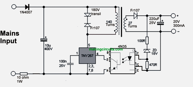
Referring at the schematic diagram of the simple 12V 500mA SMPS circuit it becomes clear below. On account of the minimal power, I employed halfwave rectifier. Voltage highs are controlled applying transil (zener diodes) 180V.

This can easily be replenished by the customary parallel composition of resistance and capacitor.

Feedback will be supplied with optocouplers, the minimum threshold is picked out purely via zener diode (ZD). ZD achieves the output voltage.

It happens to be approximately 1V above the formal voltage of ZD, due to the fact that the voltage decline of the LED optocoupler is occupied. For 19V output voltage ZD 18V is implemented.

As expected i better not force one to construct 19V supply - output voltage are typically fine-tuned by adjusting a couple of elements: - Secondary winding pertains to 1.4 z / V. - ZD is mostly about 1V under the needed voltage.

For low voltage (about 5V or less) try replacing fast diode on output with Schottky diode. Optimum power in this source in an covered power supply and 230V power is 13W.

Transformer is a compact ferrite EE. Middle column includes a cross-section of 4.5 x 4.5 mm, air gap 0.4 mm. Primary carries 140 turns of wire diameter 0.15 mm. Secondary incorporates (for 19V output) 27 turns of wire 0.4 mm.

On account of the small power the secondary is not separated to a pair of regions. To begin with, I wrapped the whole primary. The levels are interlaced primary.

Between primary and secondary i employed protective shielding - copper tape and hooked up it to the frigid end of primary (needless to say it simply cannot establish a shorter turn!).

After that I wrapped solid isolation - 12 sheets of duct tape. Subsequently I wrapped secondary. In the event of difficulty disturbance include a noise reductions circuit and / or work with a capacitor roughly 1n / Y1 between primary and secondary section. Specific guidelines are available in the datasheet of TNY263 - TNY268.

The greater component the number, the increased the prospective power. Be aware additionally the current compilation of TinySwitch-III: TNY274 - TNY280.

From this series one can find IC's making it possible for substantially more electrical power. They are able to moreover accommodate with schematic listed below, but the pinout are not the same.


12V 500ma smps circuit

You'll also like:

  • 1.  Designing a IC 723 Power Supply with Variable Voltage and Current
  • 2.  Simple 0-24V/5Amp Variable Power Supply Circuit with Transistors
  • 3.  DIY 0–300V DC Variable Power Supply – Transformerless Design
  • 4.  How to Make a Bridge Rectifier Circuit
  • 5.  Constant Current Adapter Circuit
  • 6.  Ten Channel Touch Switch Circuit

About Admin

Hey friends, Thanks a bunch for stopping by this site! I am an engineer with a Bachelor of Engineering in Electronics and Telecommunication. One of my passions is gathering information from all sorts of electronics books and tutorials. I then take that information and compile it into a language that is super easy to understand. My goal is to make those complex electronics circuit concepts and technical terms much more accessible for all the new and budding electronics engineers out there. I can also design customized circuit diagrams as required by the users.
If you have any questions related to this field, please do not hesitate to drop a comment! I am always here and ready to help you out with any queries you might have. I cannot wait to hear from you!

Reader Interactions

Comments

  1. danis says

    March 21, 2022 at 4:50 pm

    Thank you

    Reply
  2. danis says

    February 25, 2022 at 11:33 pm

    The title says 12V, while the ciruit 20V ??

    Reply
    • admin says

      March 20, 2022 at 7:23 am

      Replace the zener diode ZD with a 12 v zener to get 12 v output.

      Reply
      • danis says

        March 20, 2022 at 2:13 pm

        A zener 12V 0.5W is enough?

        Reply
        • admin says

          March 21, 2022 at 4:46 pm

          Yes, that’s enough…

          Reply
  3. Ayo says

    October 27, 2020 at 4:53 am

    Pls I am new can I get a sample from you

    Reply
    • admin says

      October 27, 2020 at 8:14 am

      sorry i do not provide ready made kits, i can only explain how to make

      Reply
  4. Ayo says

    October 18, 2020 at 1:08 am

    Pls how do you no the gauge of wire to use for smps

    Reply
    • admin says

      October 26, 2020 at 12:41 pm

      There are wire gauge (amp) tables available online

      Reply
  5. DEDY says

    August 27, 2019 at 1:03 pm

    Good thx

    Reply

Leave a Reply Cancel reply

Your email address will not be published. Required fields are marked *

Primary Sidebar

Categories

  • 3 Phase (4)
  • 8051 Microcontroller (1)
  • Arduino (11)
  • Audio and Amplifier (102)
  • Automation (8)
  • Battery Chargers (64)
  • Bicycle Projects (4)
  • Car and Motorcycle Projects (39)
  • Datasheets (10)
  • DIY Projects (5)
  • Electrical (15)
  • Free Energy (6)
  • Games Projects (2)
  • High Voltage (14)
  • Hobby Projects (30)
  • Household Circuits (2)
  • IC 555 Circuits (4)
  • Ignition Circuits (2)
  • Indicators (50)
  • Infrared (6)
  • Inverter Circuits (29)
  • Lights and Lamps (97)
  • Medical (8)
  • Meter and Tester Circuits (38)
  • Motor Driver (17)
  • New Circuits (56)
  • Oscillators (30)
  • Pets and Pests (5)
  • Power supply (81)
  • Protection Circuits (25)
  • PWM (8)
  • Remote Control (20)
  • Security and Alarm Circuit (48)
  • Sensors and Detectors (66)
  • Signal Processor (23)
  • Solar Controller Circuits (61)
  • SSR (3)
  • Temperature Controller (20)
  • Timer (25)
  • Transformerless (7)
  • Transmitters (12)
  • Tutorials (45)
  • UPS (2)
  • Voltage Regulators (57)
  • Water Sensor and Controller (29)
  • Home
  • Privacy Policy
  • Contact
  • Disclaimer
  • Copyright

© 2025 · Making Easy Circuits