Featuring 90% efficiency, this step-down buck converter can transform a 220V AC input from the mains supply into 5V, 12V, or 24V DC.
The indicated buck converter is an SMPS circuit that makes use of STMicroelectronics' IC VIPer12A.
The circuit we designed uses very few external components. It operates directly from mains AC input.
Buck Converter Design
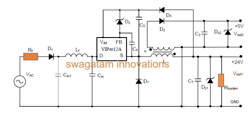
In the circuit diagram, we see the input stage. It includes a surge-limiting resistor that acts like a fuse. There is also a diode for rectifying AC and an LC filter network to reduce DC ripple.
LC Filter Functionality
The LC filter stabilizes the DC output. It also improves electromagnetic interference (EMI) response. We can add capacitor Cin1 to enhance EMI performance.
Main PWM Processor
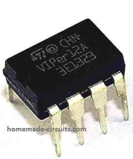
The IC VIPer12A is our main PWM processor. It handles the entire buck conversion process.
Main Features
Here are the main specifications of our configuration:
- AC Input Voltage (Vinac): 80 - 285 Vac
- Output Current (Iout): 30 mA
- Output Current (Iout): 250 mA
- Output Voltage (Vout1): +24 ± 10% V
- Output Voltage (Vout2): +5 V ± 5%
- Switching Frequency: 60 kHz
- Output Power: ~1 W
How It Works
Our circuit provides two outputs. The 24V output comes from a buck converter. The 5V output uses flyback mode.
We get feedback voltage for regulation from Vout1. This voltage also connects to the IC's Vdd pin.
This setup simplifies wiring. We only need one high-voltage diode and one capacitor (D1 and C3). This makes connections easier and cheaper.
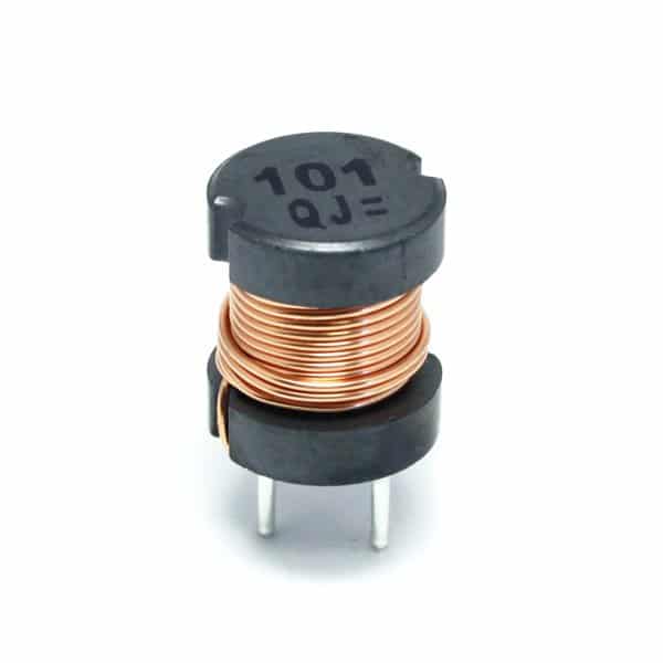
The inductor L has two windings on a common ferrite core.
The windings have specific turn ratios: N1 = 200 turns and N2 = 60 turns. Both are wound on a PANASONIC ELC10D152E ferrite core.
We installed Zener diodes Z1 and Z2 to protect the outputs from overvoltages.
We fixed a dummy load resistor across Vout1 to ensure proper regulation during open load situations.
While this resistor slightly affects efficiency, it significantly enhances the voltage regulation response of the circuit.
We used fast response, fast recovery rectifier diodes at the output. D1 is a high voltage diode to handle the high reverse voltages from the DC bus. D2 is a standard diode.
Parts List for the proposed simple SMPS buck converter circuit:
| Component | Specification |
|---|---|
| Rr | 10Ω, 1/2W |
| Rf | 10kΩ, 1/4W |
| R(load) | 4.7kΩ, 1/4W |
| Cin | 4.7 μF, 450V Electrolytic Capacitor |
| C1 | 33 μF, 50V Electrolytic Capacitor |
| C2 | 100 μF, 16V Electrolytic Capacitor |
| C3 | 1 μF, 25V Electrolytic Capacitor |
| C4 | 22 nF Ceramic Capacitor |
| Dr | Diode 1N4007 |
| D1 | Diode BA159 (fast) |
| D2 | Diode 1N4148 (fast) |
| D3 | Diode 1N4004 |
| Dz | 22V Zener |
| Dz1 | 27V Zener |
| Dz2 | 5.6V Zener |
| L1 | 0.5 mH |
| Lf | 470 μH Inductor |
| IC1 | STMicroelectronics VIPer12ADIP |
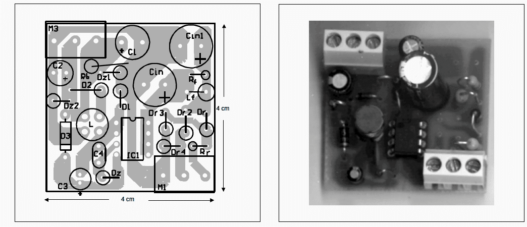
The PCB design and components arrangement of the IC VIPer12A-based SMPS buck converter circuit described above
Leave a Reply