The post explains how to make a simple electronic thermometer using a single LM324 IC and some other passive components.
The electronic thermometer does not depend on any mechanical principle, or glass, or mercury based elements, rather measures the temperature of the surrounding exclusively through semiconductor based sensors, and op amp based amplifiers.
The final reading of the temperature is achieved over a cheap voltmeter unit.
Using 1N4148 as the Temperature Sensor
A popular garden diode such as the 1N4148 is in theory a fantastic sensor for a fairly precise electronic thermometer since the voltage drop over the diode lowers by 2 mV for every single degree Centigrade increase in temperature.
As may be seen in figure 1, a fixed reference voltage is placed on the non-inverting input of the op amp. The current moving via the resistor, and thus in the diode, is likewise kept at a constant level.

Changes in the output voltage of the op amp can happen only on account of a difference in the voltage drop over the diode which in turn can only be brought on by temperature disparities.
Circuit Description
The output voltage is for this reason directly proportionate to the temperature of the diode. In the comprehensive circuit diagram demonstrated in figure 2 below, the op amp is A2 and the diode is D1.
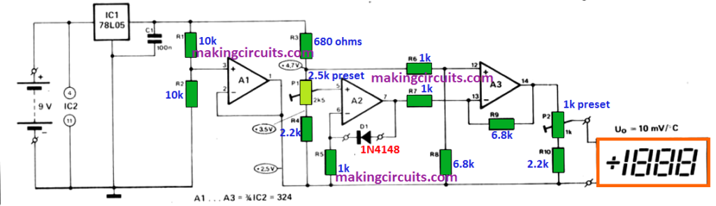
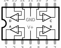
All the op amps shown in the above diagram is configured from a single LM324 quad op amp IC. The pinout details for the IC can be seen below:
The reference voltage comes from IC1 through voltage divider R3/P1/R4. The output voltage of A2 is amplified by op amp A3.
The non inverting input of A3 is additionally kept at a fixed level (once again acquired from R3/P1/R41 and the values of R6 and R8 are actually selected to ensure that 0 V corresponds to 0°C ambient.
How to Test
To allow the testing of temperatures with this electronic thermometer over and below zero without employing a dual regulated power supply, a somewhat unusual alternative was implemented.
The first necessity was a regulator, IC1, which supplies a fairly regulated and fixed reference voltage for A2 and A3. An extra amplifier, A1, produces along with R1 and R2, a voltage of +2.5 V with reference to the negative supply of the circuit.
This +2.5 V supply is subsequently applied as the 'earth' throughout the remaining circuit. Pin 11 of IC2 is as a result at -2.5 V and pin 4 at +6.5 V with reference to this 'earth' line.
The supply to the op amps is thus 'symmetrical'. The current draw of the circuit is approximately 5 mA to ensure that for momentary temperature readings a 9 V battery is going to be sufficient.
If long periods of use is demanded, an easy AC to DC adapter may be used as the supply source; which does not need to be a regulated one because of the regulation already achieved from IC1.
The majority of voltmeters will likely be acceptable as the temperature indicator display unit. The thermometer will in that case provide a range of -9.99 to +99.9 degrees Centigrade.
How to Set up
The above explained electronic thermometer circuit is calibrated by adjusting the preset P1 to attain 0 V at 0° Centigrade and subsequently P2 may be adjusted to get 0.999 V at 99.9° Centigrade.
How would you simulate this circuit in Multisim?