• Skip to main content
  • Skip to primary sidebar

Making Easy Circuits

Learn and build electronic circuits

You are here: Home / Infrared / Simple Infrared Transmitter Circuit

Simple Infrared Transmitter Circuit

Last Updated on September 22, 2021 by Admin 7 Comments

The presented simple infrared transmitter circuit design can be used in the form of an infrared remote control, with a frequency modulated tone, to operate a complementing IR receiver circuit.

How the Circuit Functions

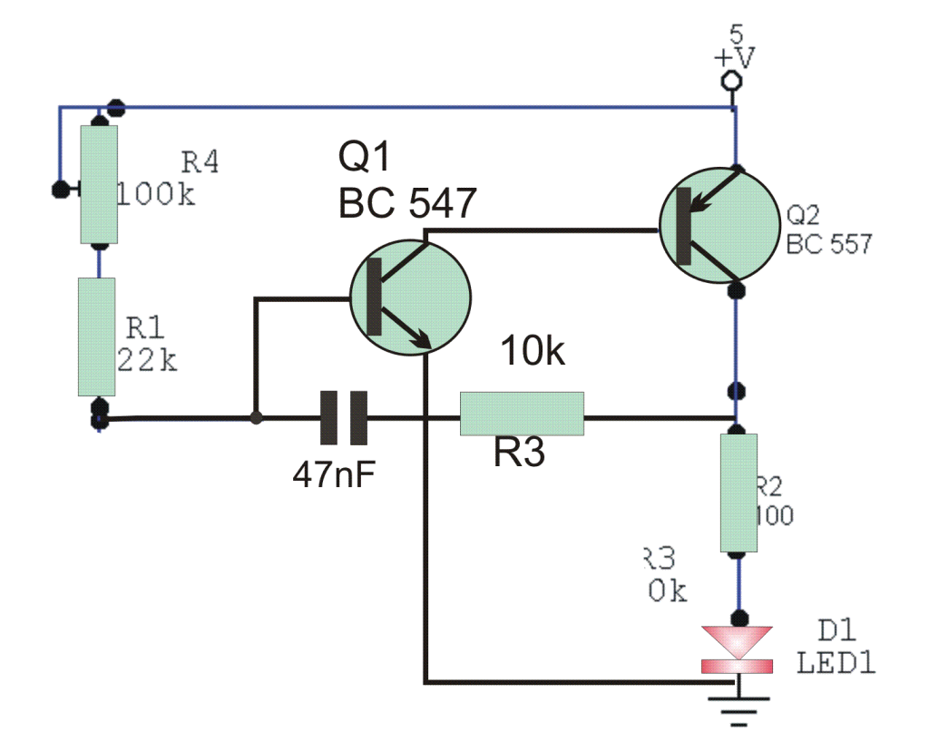
The transmitting frequency is determined by C1 and adjusted using the trimpot 100k.

The transmitter LED must be of the infrared type and more power can be achieved by connecting two LEDs in series with a series 100 ohm limiting resistor (using no less than 22).

The supply voltage which becomes the operating voltage for the infrared transmitter can also be increased to 9V in order to compensate the presence of the LED resistor.

Simple Infrared Transmitter Circuit

You'll also like:

  • 1.  How to Build a Tuned Infrared (IR) Detector Circuit
  • 2.  Infrared Motion Detector Circuit
  • 3.  How to Make a Infrared (IR) Controlled LED Emergency Lamp Circuit
  • 4.  How to Make a Model Locomotive Infrared Controller Circuit
  • 5.  How to build a Infrared Remote Control Security Lock Circuit for Automotive Applications

Tagged With: Transmitters

About Admin

Hey friends, Thanks a bunch for stopping by this site! I am an engineer with a Bachelor of Engineering in Electronics and Telecommunication. One of my passions is gathering information from all sorts of electronics books and tutorials. I then take that information and compile it into a language that is super easy to understand. My goal is to make those complex electronics circuit concepts and technical terms much more accessible for all the new and budding electronics engineers out there. I can also design customized circuit diagrams as required by the users.
If you have any questions related to this field, please do not hesitate to drop a comment! I am always here and ready to help you out with any queries you might have. I cannot wait to hear from you!

Subscribe
Login
Notify of
7 Comments
Newest
Oldest Most Voted
Inline Feedbacks
View all comments
Jari
2 years ago

Hi,
I made this circuit and it won’t work.
Is everything correct in that drawing?

0
Reply
Author
Admin
2 years ago
Reply to  Jari

Everything is correct in the drawing. It is a simple oscillator circuit. Replace the LED with a speaker and check whether it is emitting a tone or not.

Please make sure the 47nF is not connected to the emitter of Q1….it is directly connected to R3.

0
Reply
Samwel Muyengi
2 years ago

Hi everyone, I am thinking of making a multiple channel IR transmitter and receiver without using any ic ,can you help me with that?

0
Reply
Denisa Anghel
4 years ago

Hi! Can you please tell me for what are the bipolar transistors used for? Are they used as a switch?

0
Reply
Author
Admin
4 years ago
Reply to  Denisa Anghel

Hi, yes the main application of BJTs or any type of transistor is like a switch, and also like an amplifier

0
Reply
Anil Kumar. K
7 years ago

Hi I assembled this circuit. Supply voltage is 5vdc and one IR LED from a TV remote control. I got 25cms range.

Currently I am using two seperate identical circuits for driving LEFT and RIGHT LED’s of an ” Ostacles avoiding robot toy car ” . I want to use single transmitter for two IR LED’s in series on 9VDC supply. What changes should I make…..?
( You have already explained 9v connection in the article.
But I didnot understand it. Can you please explain it some other way ….? )

0
Reply
Author
Admin
7 years ago
Reply to  Anil Kumar. K

Hi, I am glad you could make it….for using two LEDs you won’t have to change anything, just connect another LED in series with D1, and use 9V as the supply…may be 100 ohm could be changed to 150 ohms, that’s all

0
Reply

Primary Sidebar

Categories

  • 3 Phase (4)
  • 8051 Microcontroller (1)
  • Arduino (11)
  • Audio and Amplifier (103)
  • Automation (8)
  • Battery Chargers (64)
  • Bicycle Projects (4)
  • Car and Motorcycle Projects (40)
  • Datasheets (10)
  • DIY Projects (6)
  • Electrical (15)
  • Free Energy (6)
  • Games Projects (2)
  • High Voltage (14)
  • Hobby Projects (30)
  • Household Circuits (2)
  • IC 555 Circuits (4)
  • Ignition Circuits (2)
  • Indicators (51)
  • Infrared (6)
  • Inverter Circuits (29)
  • Lights and Lamps (97)
  • Medical (8)
  • Meter and Tester Circuits (38)
  • Motor Driver (17)
  • New Circuits (56)
  • Oscillators (30)
  • Pets and Pests (5)
  • Power supply (84)
  • Protection Circuits (25)
  • PWM (8)
  • Remote Control (20)
  • Security and Alarm Circuit (48)
  • Sensors and Detectors (66)
  • Signal Processor (23)
  • Solar Controller Circuits (61)
  • SSR (3)
  • Temperature Controller (20)
  • Timer (25)
  • Transformerless (7)
  • Transmitters (12)
  • Tutorials (45)
  • UPS (2)
  • Voltage Regulators (57)
  • Water Sensor and Controller (29)
  • Home
  • Privacy Policy
  • Contact
  • Disclaimer
  • Copyright

© 2025 · Making Easy Circuits

wpDiscuz