The article details an uncomplicated laser beam dependent security alarm circuit that could be set up in agricultural areas and fields for detecting just about all potential intrusions, sometimes by a human being or an animal and alarming this to the user, and guaranteeing a powerful defense to the vegetation against these kinds of intrusions
The suggested laser beam burglar alarm circuit for safeguarding harvests from beasts and invaders may be seen in the picture below.
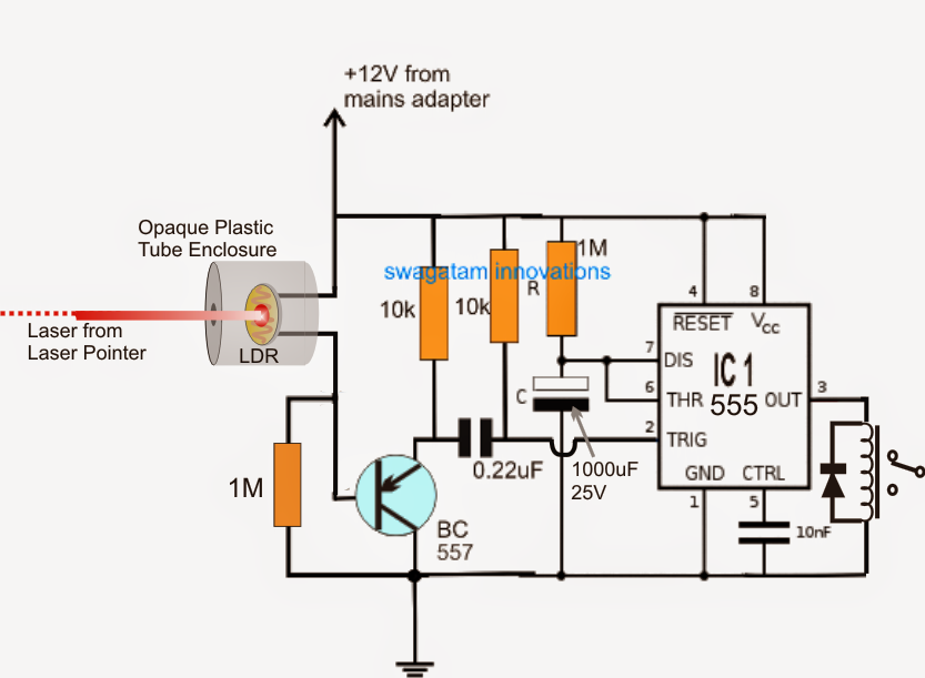
The concept presents itself remarkably simple, and utilizes an IC 555 dependent monostable multivibrator stage together with an LDR sensor.
As presented in the plan, the laser beam is drawn by means of a laser pointer circuit attached at certain matching location across the area boundary which must be guarded.
Because a laser beam carries the characteristic of concentrating over a particular position without distortions, and on a straight line, no matter what the distance may be, the target within this utility is fine-tuned over an LDR across a particular length, as determined in the diagram.
The LDR is encased inside a light proof container with a miniature opening that enables just the laser beam to come into at the same time impeding the majority of the surrounding illumination around.
Provided that the laser beam is kept centered over the the LDR, the resistance of the LDR is turned on the very least degree that can be around 10K to 50K roughly as determined by the specific LDR technical specs.
The minimal resistance from the LDR provides a very high potential at the base of the connected BC557 transistor making this dormant. Consequently this retains the pin#2 of the IC555 monostable at an increased potential and the output of the IC at logic zero, to ensure that the relay is kept turned OFF.
At this point in a case when an intruder (a human being or creature) tends to make an an effort pass by the secured line of entrap, intersects or obstructs the laser beam, which at once results in the LDR resistance to maximize and activate the BC557 device through the 1M resistor.
The BC557 acts to this and fires, grounding pin#2 of the IC as well as setting off the monostable actions.
The above method pushes the pin#3 of the IC to get high and activate the relay, the relay contacts in all probability being associated with an security alarm, triggers the security alarm, cautioning the field proprietor about the intrusion.
The alarm goes on to "shout" for a few minutes of time determined by the magnitudes of R and C, whose quantities are precisely proportional to the period of the security alarm activation interval.
The above mentioned laser alarm circuit can be set up across most of the corners of farm for confirming highest possible and 100% safety for the invaluable harvests and for providing a relaxing sleep to the field possessor.
Leave a Reply