• Skip to main content
  • Skip to primary sidebar

Making Easy Circuits

Learn and build electronic circuits

You are here: Home / Hobby Projects / Simple Light Activated Switch Circuit

Simple Light Activated Switch Circuit

Last Updated on January 10, 2018 by Admin Leave a Comment

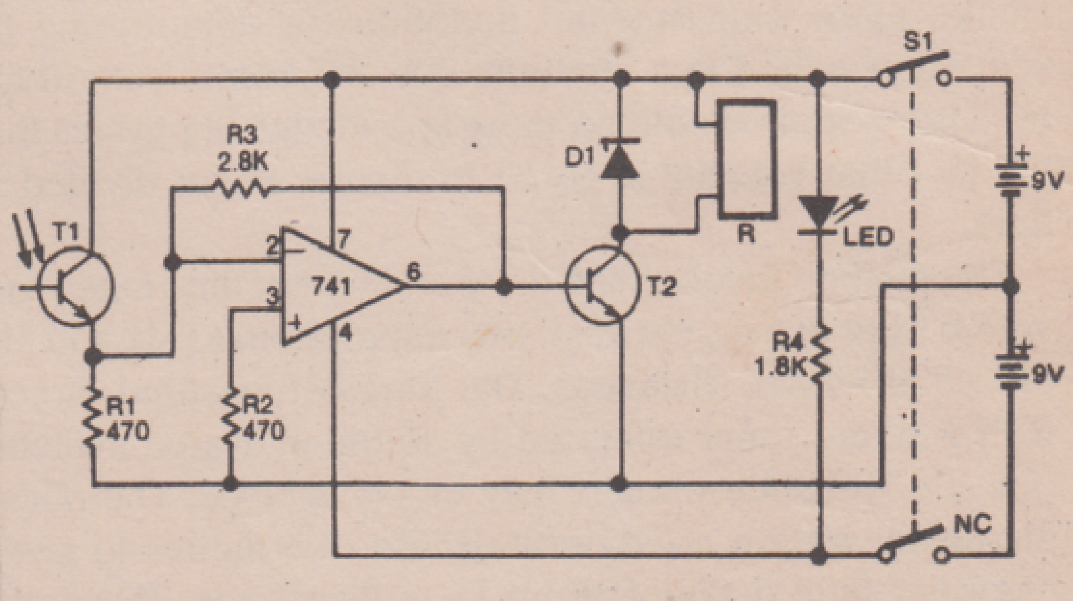
The light activated switch circuit works on a very basic principle, that of amplification of the current produced by a photo-transistor when light impinges upon it. The current is amplified by op-amp 741 that drives T2, energising a relay. The circuit shown can be used to activate a relay with a conventional torch up to reasonable distances for use at home. The controlled apparatus will remain switched on (or off) as long as the torch’s light falls on T1

It will be noted that the base of photo-transistor Tl is not connected., The photo-transistor must be protected from ambient light by some sort of protective tube, or it might switch on the relay when sufficient IR light is available. The output of the op-amp is sufficient to energise a sensitive relay. Transistor T2 may be eliminated, if the relay is capable of working on currents less than 8mA. However, if T2 has to be used, almost any type of silicon switching transistor may be used for amplification; the particular make depends on the power consumed by the relay. The LED power-on indicator requires about 10mA, and may be eliminated if so desired.


simple light activated switch circuit

You'll also like:

  • 1.  Small Easy Circuit Projects
  • 2.  Chirping Bird Circuit
  • 3.  “Wheel of Fortune” Game Circuit
  • 4.  How to make a Proximity Detector Circuit Using IC 555
  • 5.  Proximity Detector Circuit – LC Tuned IC CS209
  • 6.  Types of Biometric Sensors and Its Working

About Admin

Hey friends, Thanks a bunch for stopping by this site! I am an engineer with a Bachelor of Engineering in Electronics and Telecommunication. One of my passions is gathering information from all sorts of electronics books and tutorials. I then take that information and compile it into a language that is super easy to understand. My goal is to make those complex electronics circuit concepts and technical terms much more accessible for all the new and budding electronics engineers out there. I can also design customized circuit diagrams as required by the users.
If you have any questions related to this field, please do not hesitate to drop a comment! I am always here and ready to help you out with any queries you might have. I cannot wait to hear from you!

Reader Interactions

Leave a Reply Cancel reply

Your email address will not be published. Required fields are marked *

Primary Sidebar

Categories

  • 3 Phase (4)
  • 8051 Microcontroller (1)
  • Arduino (11)
  • Audio and Amplifier (102)
  • Automation (8)
  • Battery Chargers (64)
  • Bicycle Projects (4)
  • Car and Motorcycle Projects (39)
  • Datasheets (10)
  • DIY Projects (5)
  • Electrical (15)
  • Free Energy (6)
  • Games Projects (2)
  • High Voltage (14)
  • Hobby Projects (30)
  • Household Circuits (2)
  • IC 555 Circuits (5)
  • Ignition Circuits (2)
  • Indicators (50)
  • Infrared (6)
  • Inverter Circuits (29)
  • Lights and Lamps (97)
  • Medical (8)
  • Meter and Tester Circuits (38)
  • Motor Driver (17)
  • New Circuits (56)
  • Oscillators (30)
  • Pets and Pests (5)
  • Power supply (80)
  • Protection Circuits (25)
  • PWM (9)
  • Remote Control (20)
  • Security and Alarm Circuit (48)
  • Sensors and Detectors (66)
  • Signal Processor (23)
  • Solar Controller Circuits (62)
  • SSR (3)
  • Temperature Controller (20)
  • Timer (25)
  • Transformerless (7)
  • Transmitters (12)
  • Tutorials (45)
  • UPS (2)
  • Voltage Regulators (57)
  • Water Sensor and Controller (29)
  • Home
  • Privacy Policy
  • Contact
  • Disclaimer
  • Copyright

© 2025 · Making Easy Circuits