This simple radio circuit is in essence a crystal radio having an audio amplifier that is definitely pretty sensitive and obtains a number of powerful programs in a given area by using a 10 foot antenna.
Lengthier antennas is going to deliver a more powerful reception nevertheless the selectivity could be compromized and powerful channels may perhaps be over heard in the background of less strong receptions.
Applying an extended wire antenna, the ability to selecect precisely could be increased by attaching it to one of the central points on the coil rather to the passageway of the capacitor and the coil.
Certain interconnection across earth becomes necessary although you may find that positioning out in the open over a cement piece and just letting the extended headphone terminals to set on the cement would seem quite satisfactory for the listening of the local stations.
The inductor should be wound using 200 turns of 28SWG enameled copper wire over a 7/8 diameter, 4 inch long PVC pipe, which might create around 220 uH value for the inductor.
The inductor could be wound with terminals after every 20 spins to ensure the diode and antenna associations may very well be determined to get most effective outcomes which often becomes 60 turns through the antenna ending with the diode.
The diode could be a germanium for optimal outcomes, yet silicon diodes can even perform if your transmission is actually powerful.
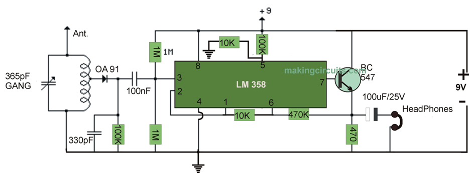
The carrier frequency is stripped away from the rectified signal with the cathode of the diode through the 300 pF cap as well as the audio frequency is flushed with the 0.1uF capacitor into the non-inverting input of the relevant op-amp which performs like a high impedance buffer stage.
The other op-amp stage improves the voltage level approximately FIFTY times and is particularly coupled to the prior via the 10K resistor. In case the units of 100K and 1 Meg resistors happen to be dissimilar in value (1%) it might be imperative to possibly work with better equivalent values or squeeze in a capacitor in line together with the 10K resistor to maintain the DC voltage within the transistor emitter somewhere between 3 and 6 volts.
A different strategy requires you to limit the overall gain using a scaled-down feedback resistor (470K).
High impedance earphones definitely will give improved hearing experience, although stereo type headphones will likely do the job. The proposed simple radio circuit works with approx 10 mA coming from a 9 volt battery.
Note: The LM358 is a class B amplifier with no bias and produces excessive crossover distortion when used in audio applications. A better choice is the LM1458, which could be replaced for the shown LM358.
Leave a Reply