• Skip to main content
  • Skip to primary sidebar

Making Easy Circuits

Learn and build electronic circuits

You are here: Home / Inverter Circuits / Sine Wave Inverter Circuit using PIC16F72

Sine Wave Inverter Circuit using PIC16F72

Last Updated on October 10, 2025 by Admin 80 Comments

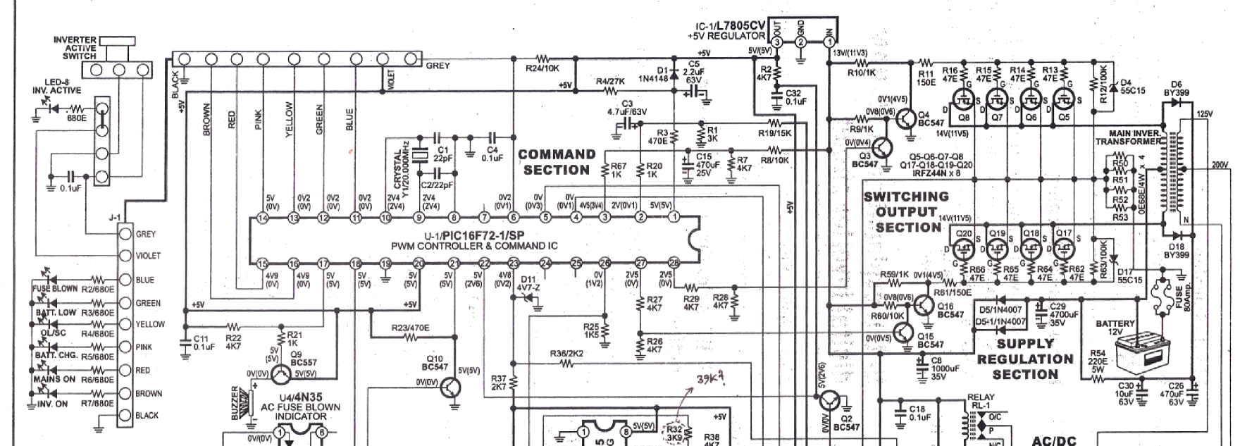
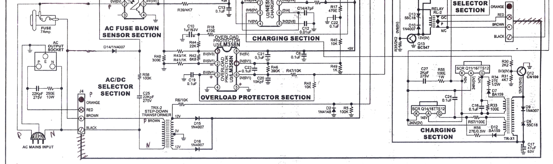
The post details comprehensively regarding how to build a pure sinewave inverter circuit using microcontroller circuit with PIC16F72

The following image shows the complete circuit diagram of the sinewave inverter, the images are divided into two in order to fit inside the page, please join them together after printing the two images.

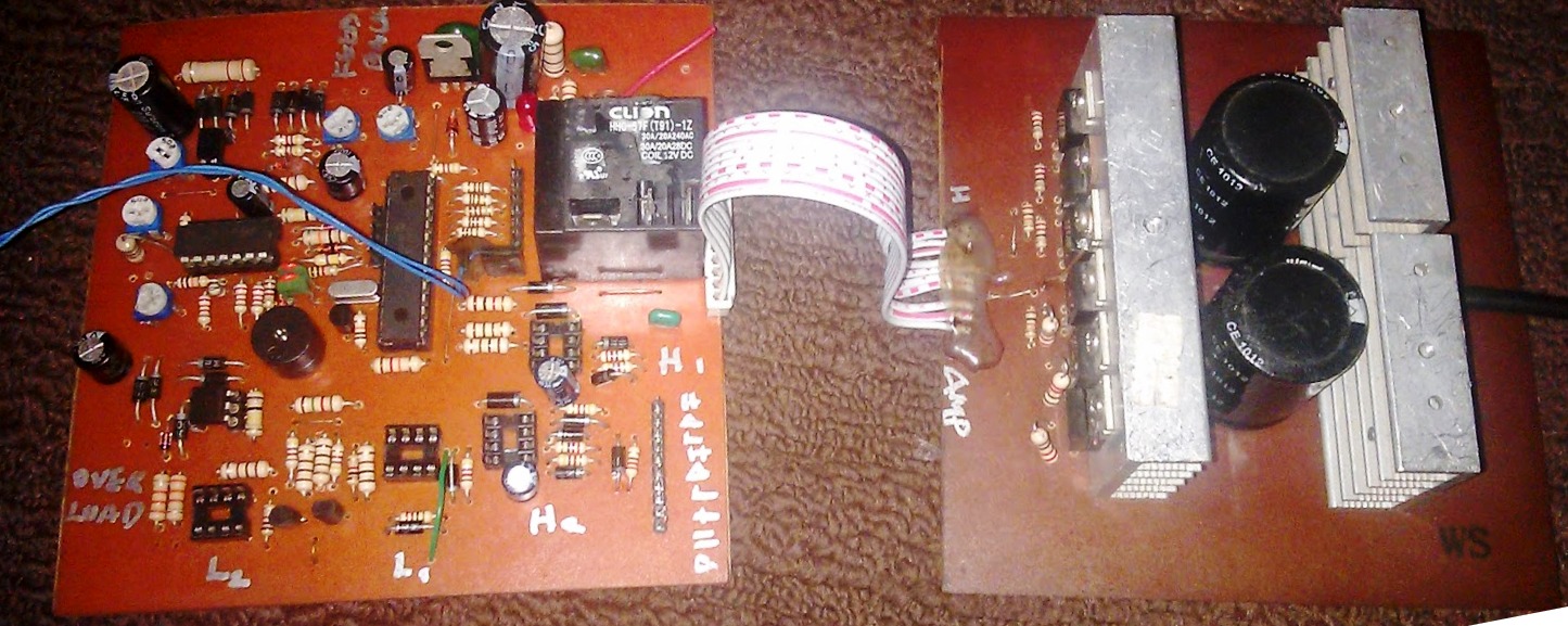
The following image shows the built prototype which tested using a 1200 watt load successfully

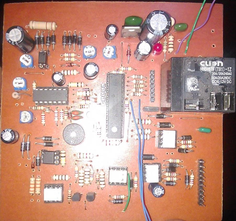
The close up of the mother board of the proposed sinewave inverter using PIC16F72 can be witnessed in the following image

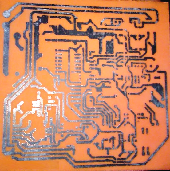
This picture shows the PCB track layout for the proposed inverter design.

49636983LCD

pic16f84a-sinewave-INVERTER

sine_power_002

sinewave

SN73_LCD

Branded inverter

Hex files and PIC code along with PCB designs of this pure sine wave inverter circuit using PIC16F72 can be downloaded from the above shown links,.........Hope this helps!!

You'll also like:

  • 1.  Transformerless H-Bridge Inverter Circuit
  • 2.  Make this Sine Wave Inverter Circuit using Bubba Oscillator
  • 3.  Simple 100 watt to 500 watt Inverter Circuit
  • 4.  100 watt Inverter Circuit Using 2N3055 Transistors
  • 5.  How to Make a Optimizing Grid and Solar Electricity in Parallel with an Inverter
  • 6.  Inverter Circuit Using Arduino

Tagged With: Inverter, PIC16F72, Sine, Wave

About Admin

Hey friends, Thanks a bunch for stopping by this site! I am an engineer with a Bachelor of Engineering in Electronics and Telecommunication.

One of my passions is gathering information from all sorts of electronics books and tutorials. I then take that information and compile it into a language that is super easy to understand.

My goal is to make those complex electronics circuit concepts and technical terms much more accessible for all the new and budding electronics engineers out there.

I can also design customized circuit diagrams as required by the users.

If you have any questions related to this field, please do not hesitate to drop a comment!

I am always here and ready to help you out with any queries you might have. I cannot wait to hear from you!

Reader Interactions

Comments

  1. Adnan says

    October 14, 2025 at 12:26 am

    Your schematic does not match with the firmware you linked in the article. One example in your schematic uses a center-tap transformer. But the firmware uses a full bridge transformer that is drive by a H-bridge driver circuit.

    Reply
  2. Kebong kufre says

    September 23, 2025 at 3:07 am

    how do I get the circuit

    Reply
  3. BRaj says

    August 7, 2024 at 6:40 pm

    Hello, I want the design of DSP based true sine wave circuit design and PCB layout with programming files , let me know if available with you.

    Reply
    • Admin says

      August 27, 2024 at 1:13 pm

      Hi BRaj, sorry it is not available to me right now…

      Reply
  4. Sanjay says

    May 16, 2024 at 9:55 am

    can increase the output power of an inverter

    Reply
    • Admin says

      May 21, 2024 at 12:32 pm

      yes, by increasing the transformer, MOSFET and battery power ratings

      Reply
      • Sanjay says

        May 29, 2024 at 2:03 pm

        Thank you for your reply

        Reply
  5. Muhammad Arshad says

    November 20, 2023 at 2:06 pm

    Bro send link for pic 16 F 72

    Reply
    • Admin says

      November 25, 2023 at 10:53 am

      It is given in the article; you can download them.

      Reply
    • swag says

      March 8, 2025 at 9:18 am

      yes please send it to me also…

      Reply
      • Admin says

        March 8, 2025 at 9:19 am

        let me try it….

        Reply
  6. Aron says

    September 29, 2023 at 8:49 am

    This article is very helpful!

    Reply
    • Admin says

      September 29, 2023 at 8:50 am

      Thank you Aron, and Glad you found the post helpful!

      Reply
« Older Comments

Leave a Reply Cancel reply

Your email address will not be published. Required fields are marked *

Primary Sidebar

Categories

  • 3 Phase
  • 8051 Microcontroller
  • Amplifier Circuits
  • Arduino
  • Audio and Amplifier
  • Automation
  • Battery Chargers
  • Bicycle Projects
  • Car and Motorcycle Projects
  • Datasheets
  • DIY Projects
  • Electrical
  • Free Energy
  • Games Projects
  • High Voltage
  • Hobby Projects
  • Household Circuits
  • IC 555 Circuits
  • Ignition Circuits
  • Indicators
  • Infrared
  • Inverter Circuits
  • Lights and Lamps
  • Medical
  • Meter and Tester Circuits
  • Motor Driver
  • New Circuits
  • Oscillators
  • Pets and Pests
  • Power supply
  • Protection Circuits
  • PWM
  • Remote Control
  • Security and Alarm Circuit
  • Sensors and Detectors
  • Signal Processor
  • Solar Controller Circuits
  • SSR
  • Temperature Controller
  • Timer
  • Transformerless
  • Transistors
  • Transmitters
  • Tutorials
  • UPS
  • Voltage Regulators
  • Water Sensor and Controller
  • Home
  • Privacy Policy
  • Contact
  • Disclaimer
  • Copyright

© 2025 · Making Easy Circuits