I was forced to address the issue once and for all after receiving a growing number of reader complaints about burning LEDs related to my previously released transformerless 1 watt LED driver circuit. With the exception of the "switch ON delay feature," that was specifically created and implemented to the circuit to potentially fix the problem with the burning LED issue, the power supply portion of the circuit covered here is precisely the same as it was in the prior setup.
It is very dangerous to touch any of the circuits listed below when they are switched on and open, since they are not separated from the mains AC. Handling these circuits requires a high degree of safety concern.
Reducing Capacitive Power Supply In-rush Surge
The first switch ON surge, which continued to damage the 1 watt LEDs attached at the circuit's output, was definitely the reason of the problems I was getting.
This issue is quite typical of all capacitive power supply types, and it has severely damaged these power supply types' reputations.
Because they are afraid of the aforementioned consequences if they incorporate bigger value capacitors, a lot of beginners as well as experts typically choose lower value capacitors.
Capacitive transformerless power supply, on the other hand, are excellent, inexpensive, and small AC to DC adapter circuits that require minimal construction work, in my opinion.
When the ON power surge is properly addressed, these circuits evolve into pristine and may be utilized without worrying about damaging the output load, particularly an LED.
The Process of Development of Surge
When a switch is turned on, the capacitor behaves like a short circuit for just a few microseconds before it charges. Only thereafter does it add the necessary reactance to the associated circuit, ensuring that just the right proportion of current flows through it.
But occasionally the first few microseconds of short circuit throughout the capacitor is sufficient to damage the accompanying load and causes an enormous spike to the associated susceptible circuit.
In case the associated load is prevented from reacting to the first switch-ON shock, the aforementioned scenario may be successfully verified; in simple terms, the very first surge could be eliminated by retaining the load turned OFF before an appropriate time has arrived.
Employing a Delay Function
By including a delay function in the circuit, this may be accomplished rather simply. And that's precisely what I have incorporated into my suggested circuit for a high-watt LED driver which is surge guaranteed.
As is customary, the illustration displays an input capacitor, a bridge rectifier, and finally the somewhat standard capacitive power supply.
a couple of 10 K resistors, two capacitors, a transistor, and a zener diode make up the following step, and these forms the crucial delay timer circuit.
The two resistors and capacitors prevent the transistor from switching ON when the power is turned on before the two capacitors have been completely charged and the biasing voltage reaches the transistor base, which takes around two seconds. subsequently that, the attached LED illuminates.
The two-second delay extension is likewise the result of the zener.
In order for the procedure to recur and force the surge prevention to activate each time, the 1N4007 diode between one of the 10K resistors and the 100 K resistor between one of the 470uF capacitors assist the capacitors in discharging quickly after the electrical supply is turned off.
To increase the power output, additional LEDs can be hooked up in series, but not beyond 25 can be used.

Reader complaints (transistor gets hot, resistors burn)
Although the above idea is fantastic, it most likely won't function effectively with the suggested high voltage capacitor power supply.
Before the circuit is entirely trouble-free, much study must be done on it.
The transistor in the circuit above additionally becomes very hot throughout the operation, and the resistors in the circuit above cannot tolerate the high current needs.
Lastly, we may state that the circuit shouldn't be used in practice until the aforementioned idea is fully investigated and made consistent with a capacitive transformerless power supply.
A Much Safer and Stronger Concept
Despite the failure of the aforementioned concept, high voltage capacitive power supply are still viable.
We have a unique method for resolving surge problems and strengthening the circuit's resilience.
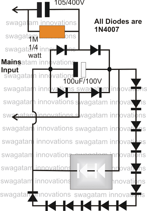
This is accomplished by connecting a number 1N4007 diodes in parallel to the linked LEDs or in series at the output.
Now let's examine the circuit:

It's nonetheless early in the process because the circuit mentioned above has not been tested for several months, however I have no reason to believe the capacitor's surge will be sufficiently powerful to cause damage to the 300V, 1 amp rated diodes.
The LEDs will be safe as long as the diodes are.
To support additional LEDs, extra diodes might be connected in series.
Making Use of a Power Mosfet
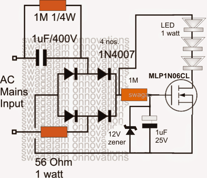
As seen in the accompanying picture, the initial circuit effort, which appeared to be susceptible to surge consequences, may be successfully fixed by swapping out the power BJT with a 1 amp mosfet.
Since the mosfet is a voltage-controlled device, the gate current turns into irrelevant in this situation, thus a large 1M resistor functions flawlessly. The high value ensures that the resistor doesn't heat up or burn when the power switch is first turned on. Additionally, it makes it possible to employ a capacitor with a fairly small value for the necessary delay ON surge suppression capability.

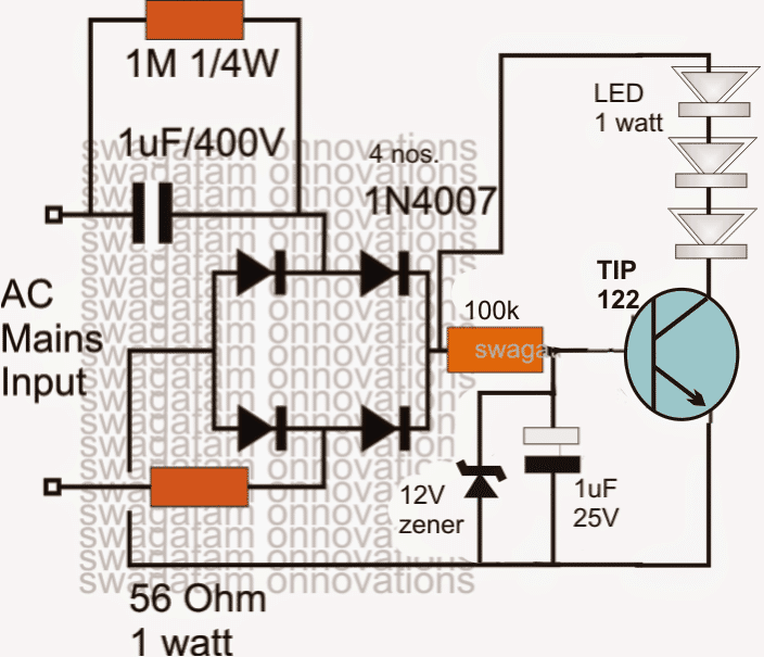
After some research, it was discovered that the high voltage transistor in the first picture was not necessary. Instead, a high current Darlington TIP122 transistor, which is depicted in the next illustration, could be used in its place.
In reality, it compels the high voltage to decrease to the designated permissible safe boundaries of the LEDs and the transistor, rendering the high voltage surge from the capacitor useless toward the high current specifications of the transistor and the LEDs without causing any harm to these.
Additionally, the TIP122 permits the application of a low value capacitor at the transistor's base to provide the necessary delayed switch ON operation, as well as a high value base resistor to ensure that it doesn't overheat or burn off over time.

Making Use of a Power BJT
When utilized in a common collector mode, the aforementioned configuration further enhances protection and suppresses surges, as seen below:

Leave a Reply