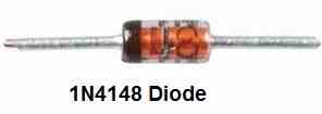
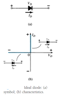
Diodes are divided into two categories: germanium diodes and silicon diodes, with the silicon diode being the most popular. In germanium diodes, forward conduction starts at around 0.2 V. This […]
RC Passive and Active Filters Explained
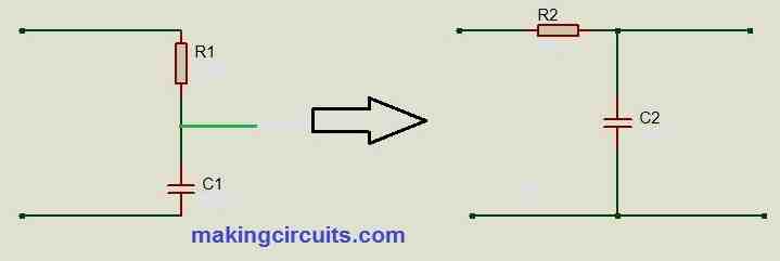
In this post we are going to learn about RC (resistive and capacitive) frequency filters and we will be simulating each of the discussed frequency filters using proteus software. We […]
12 Best Oscillator Circuits Explained
The high input impedance and high gain of the FET encourage ease and efficiency in multiple transistorized oscillator circuits. often, the FET can be utilised directly in transistor circuits and […]
26 Best Alarm Circuits Explained

In this article we will discuss about many useful and best alarm application circuits. High Power Alarm Driver Circuit In such a circuit, a less powered SCR is employed to […]
Semiconductor Diodes – Internal Structure and Working Explained
The earliest electronic component that was launched was actually the diode. It is the most basic of semiconductor units yet performs a incredibly crucial role in electronic circuits, possessing features […]
IC 555 Pinouts and Working Explained
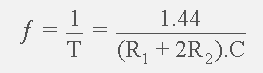
In this post we comprehensively discuss the pinout details of the timer IC 555 and the working of these pinouts in actual practical circuits. We also learn the various formulas […]