The TL431 is a popular adjustable precision shunt regulator integrated circuit that can be used as a voltage reference, precision current sink, or voltage regulator.
Below are the electrical characteristics and technical specifications of the TL431:
Voltage Reference:
- Reference Voltage Range: 2.5V to 36V
- Reference Voltage Tolerance: ±0.5% typical at 25°C
- Reference Voltage Temperature Coefficient: 50 ppm/°C typical, 100 ppm/°C maximum
Output Voltage Range:
- Adjustable output voltage range: 2.5V to 36V
- Output voltage tolerance: ±2% maximum over full temperature range
Operating Conditions:
- Operating temperature range: -40°C to +105°C
- Operating voltage range: 2.5V to 36V
- Quiescent current: 1.0mA typical, 3.0mA maximum
Other Features:
- Low dynamic output impedance: 0.2Ω typical
- Sink current capability: 1mA to 100mA
- Reference input current: 0.5μA typical, 2.0μA maximum
- Temperature stability: 50 ppm/°C typical, 100 ppm/°C maximum
The TL431 has a variety of applications including voltage regulation, voltage monitoring, and precision current sinks. It is commonly used in power supply circuits, battery charging circuits, and voltage reference applications.
Pinout Configuration
The pinout shown in Figure 1 is the most common and it applies to the TO-92 package, but this component also exists in a SO-8 SMD package.

Symbol and Internal Schematic
Figure 2 shows the symbol and Figure 3 shows the internal schematic of this component. The anode must be connected to ground. The reference pin is used to choose the reference voltage on the cathode.


On the internal schematic, we can see that this circuit consists of four sub-functions: a transistor (power device) that sets the potential between the cathode and the anode according to the current injected into its base by the operational amplifier.
The operational amplifier is powered between the cathode and the anode. Next, we find the voltage reference itself (Vref), which is connected to the negative input of the amplifier. Finally, a diode is used to protect the transistor and the amplifier in case of a polarity reversal.
How to Use TL431
Now, we will explain how to use this component.
Figure 4 shows the typical application schematic.
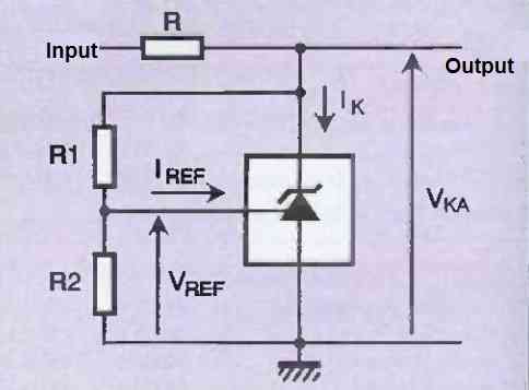
Resistors R1 and R2 set the value of the output voltage V, and resistor R limits the current in the internal transistor of the TL431. We calculate the value of R1 and R2 as follows:
VKA = VREF (1 + R1/R2) + R1.IREF
VREF and REF are fixed by the manufacturer at approximately 4 pA for REF and 2.5 V for VREF. So, we only need to determine R1 and R2 for the desired reference voltage V.
If we remove resistor R2 from the schematic in Figure 4 and connect the
Reference pin to the cathode (R1=0), then we are in the particular case of Figure 5.

This is the simplest usage schematic that we can consider with the TL431. In this case, we cannot adjust the reference voltage (V), as it will be fixed at 2.5 V.
Now, all that remains is to calculate the value of resistance R. To do this, you need to know the previously calculated voltage V, the minimum input voltage (the minimum voltage expected from the battery), and the current consumed by the circuit connected to the output.
Calculations
The calculation of this resistance must be done carefully, it is essential that the current Ik is always greater than or equal to 1 mA (it is even preferable to take a small margin: for calculations, take Ik = 2 mA). So to calculate R:
R = (Vinput - VKA) / Ioutput + IK + (VKA - VREF / R1)
To illustrate the theoretical aspects that we have developed above, we offer you a first example of implementation.
Low Battery Monitor Circuit using TL431
The diagram in Figure 6 allows the implementation of a monitoring device for a power supply by batteries or cells.
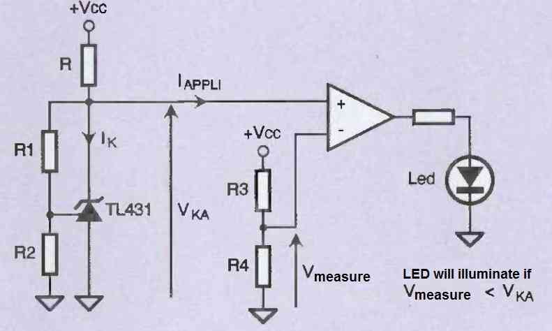
To better understand, let's give a concrete example. We power a device with a 9V battery, which we want to use until the voltage at its terminals approaches 5V.
If we refer to the diagram in Figure 6 above, we will set the reference voltage to 2.5V (as discussed earlier) with R1=0Ω and R2=not connected. Then, we will choose a voltage divider with a ratio of 1/2 with R3 = R4 = 47 kΩ.
The comparator will set its output to a low state when VMEASURE is greater than VKA (in other words, when Vcc is greater than 5V), and then to a high state when VMEASURE is less than VKA (Vcc less than 5V).
In the latter case, the comparator output will power the LED to warn the user that the voltage available at the battery terminals is below the limit set by the board designer.
It should be noted that the value of resistance R will be calculated as we have seen previously, taking into account the current in the TL431, in the positive input of the comparator, and if applicable, in another circuit if the reference voltage is used for another function.
Simple LED Monitor Circuit using TL431
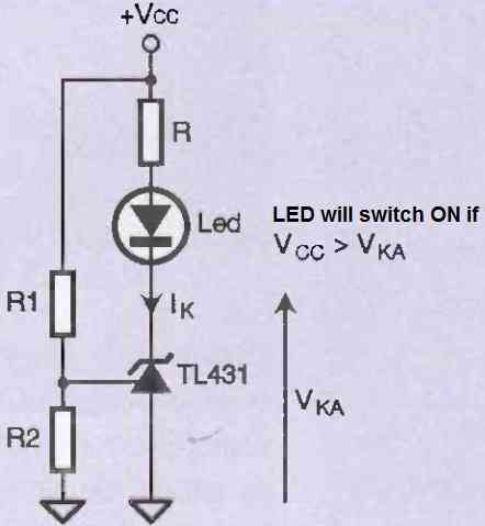
Figure 7 above represents another, simple LED monitor circuit. Many TL431 manufacturers have improved this circuit by offering versions with lower reference voltages (1.25V instead of 2.5V) and requiring much lower Ik currents (some pA or nA instead of 1mA). In this category, for example, we can mention the TS431 and TS432.

hi admin,
I would like to support me with an electronic diagram. I need to buy a power supply that have +12v, -12v and +5v. for each rail I would like to have a voltage detector. if the voltage is less with 0.5 v, then I want to have a red led on. if is high with 0.5 v, then another led (yellow) will be on. when the voltage have the nominal value, then a green led will be on. a RGB led can b an option ( not mandatory) tl431 can be also used as a voltage reference + lm339.
the next feature is to have a delay. this means to interupt the power supply output (all 3 rails) with a relay, after 2 seconds. also, if any rail have a fault, over voltage 1 v (adjustable) more than the nominal, then , the relay should be turned off (cut the output power). also, a meter with 4 LEDs that display the load per each rail – 25%, 50%,75% and 90%will be good. I will calculate the values for the resistors if you tell me which I should modify. and the last one, will be a fault led. if the fuse for one rail is down, then a red light will.indicate the fault for each rail. of course I will pay for this.for the PCC I will take care
Hi, yes this circuit can be made, but there are many things to take care in this circuit.
LM339 can be used for checking all the 3 voltage rails and TL431 can be used as reference. For +12V, -12V and +5V we can make low voltage, normal voltage and high voltage indication by 3 LEDs.
For example green LED for normal voltage, red LED when voltage is around 0.5V low and yellow LED when voltage is around 0.5V high. The 2 second delay for relay is also possible. After power ON, relay can wait for 2 seconds and then connect all 3 outputs. If any voltage is going too high, relay can be switched OFF and all outputs will be disconnected.
Fuse failure indication also can be added. If fuse of any one rail is blown, separate red LED can show which rail fuse is failed. The 25%, 50%, 75% and 90% load indication is also possible but for this we need to sense the current of each rail. So I will need to know the maximum current available from +12V, -12V and +5V.
Also the exact resistor values depends on the actual voltage limits and current ratings. Without knowing these values, I cannot give correct resistor values.
So yes complete circuit is possible with LM339, TL431, transistors and relay. RGB LED can also be used but separate LEDs will be more easy to understand.
If you give me the current rating of each rail and exact voltage limits you want, then the circuit and resistor values can be worked out.